Headset Calibration Tutorials
In order to correctly track the pose of an augmented or virtual reality headset, FusionHub combines data that’s natively acquired on the HMD with outside-in optical tracking data. To fuse these two data sources correctly the data needs to be in the same coordinate frame.
In most cases the native coordinate frame of a headset, providing either inertial (IMU) or inside-out tracking data, is well aligned with the headset’s optical coordinate system already by factory calibration. Therefore we need to find the alignment of the outside-in tracking frame to the native tracking system of the headset. Below we describe the calibraion procedure that’s needed to achieve this.
Varjo XR-4
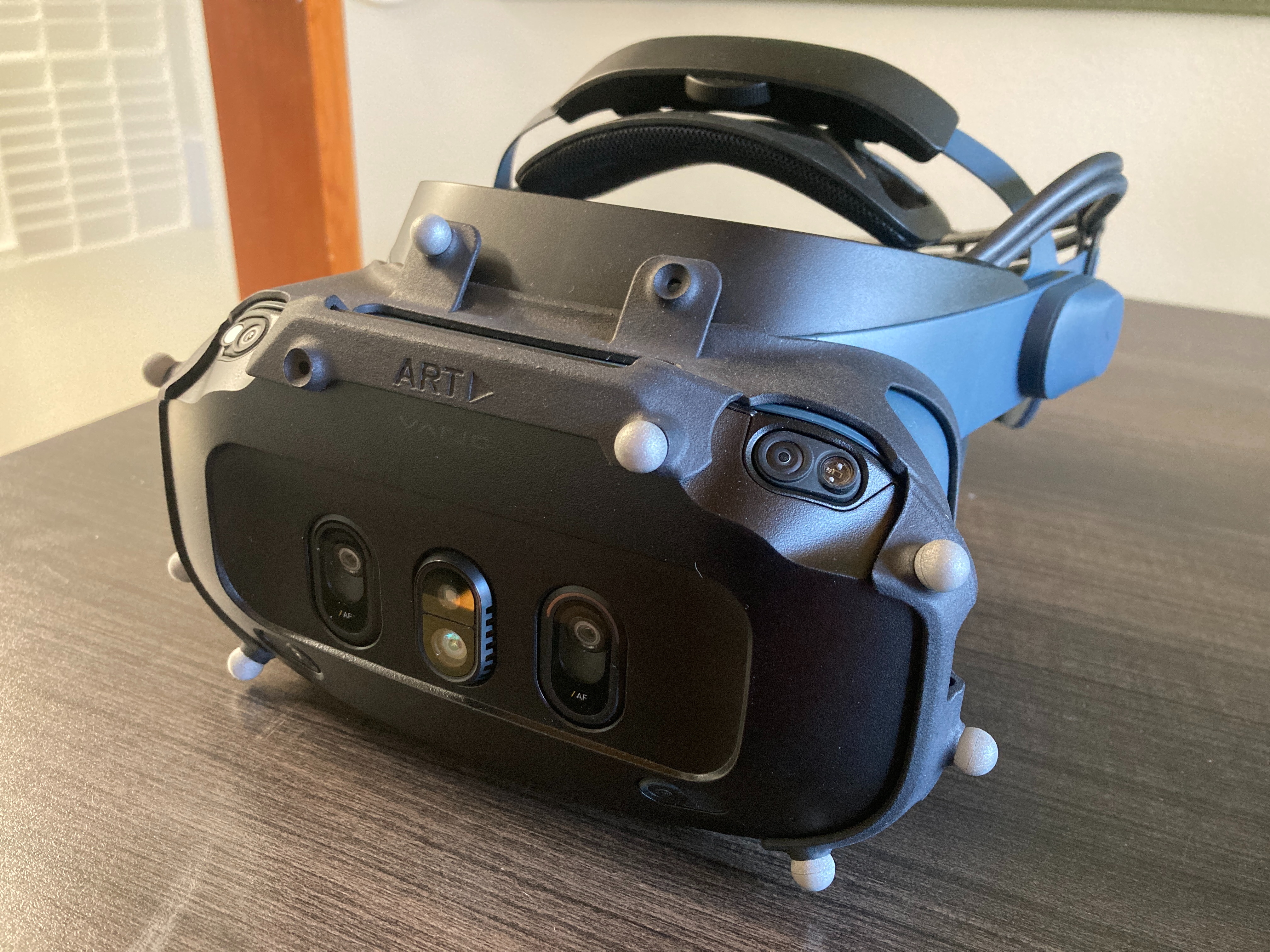
The Varjo XR-4 HMD reports its IMU (gyroscope + accelerometer) data, delivered through the Varjo HMD bridge node. Global position and orientation come from an outside-in optical system like ART that tracks a rigid marker body attached to the headset, delivered through the optical source node as OpticalData. See a photo of the XR-4 Focal Edition with an ART optical tracking target attached.
These two sensors sit on the same headset but report in two different coordinate frames: the IMU has its own axis convention, and the optical marker body is mounted at an unknown rotation relative to it. To fuse the smooth, high-rate IMU with the drift-free, globally-referenced optical pose, the fusion filter needs to know the fixed rotation that aligns the IMU frame to the optical frame.
IMU-Optical calibration recovers that alignment quaternion. As the headset is rotated, the IMU’s measured angular velocity and the optical system’s measured orientation change describe the same physical rotation seen in two frames. Collecting enough diverse rotations lets the solver recover the single rotation that maps one frame onto the other.
Once solved, the alignment is written into the IMU-Optical Fusion filter (SensorFusion.alignment). Directly modifying the optical target definition of the outside-in tracking camera system is also possible. From then on our imu-optical fusion combines Varjo IMU + DTrack optical into one consistent FusedPose, which is sent back to Varjo Base for rendering.
What you need before starting
-
DTrack Optical source node in the graph, connected to the ART controller (ATC). The headset’s marker body must be calibrated on the ATC and actively tracked, and its 6d pose must be streaming into FusionHub. Start the measurement and configure the UDP data output in the ART DTrack frontend, then confirm the optical source node in FusionHub shows incoming data.
-
Varjo HMD node in the graph, bridged to the Varjo Base plugin, so the headset’s IMU is available as an
Imustream. (Requires thevarjo_hmdlicense feature. The node also applies gyro autocalibration before forwarding the IMU downstream.) -
IMU-Optical Fusion node (
fusion, the EKF) - the apply target. This is the filter that fuses IMU + optical into the finalFusedPoseand carries the calibration result in itsSensorFusion.alignmentslot. -
IMU-Optical Intercalibration node with its Calibration Type set to IMU to Optical (
imuOptical) in the node editor’s properties panel. This is the default type.
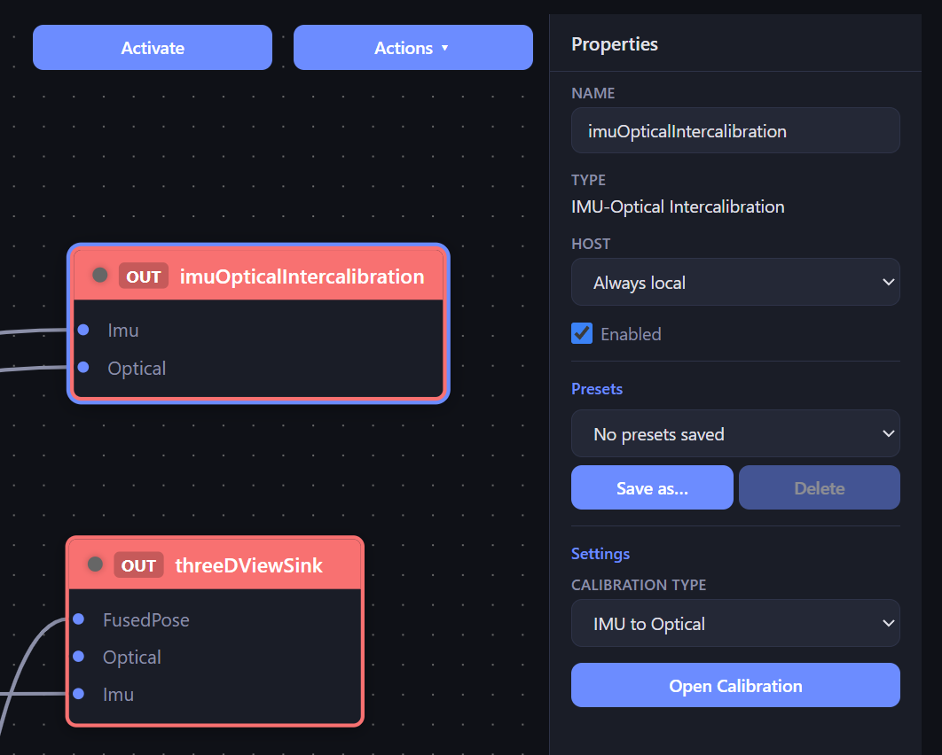
The node editor is the source of truth: wire the inputs there. The Calibration page only starts/stops the run and shows what is wired. See an example of a complete filter arrangement for differential pose tracking and intercalibration below.
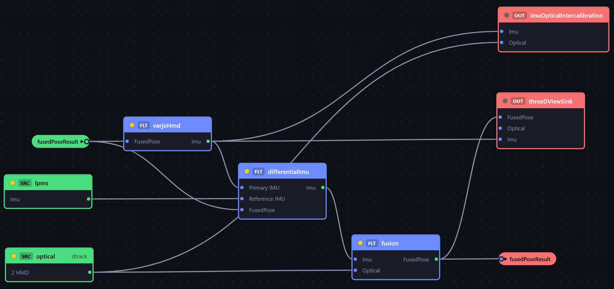
Wiring the calibration node
With the Intercalibration node’s type set to imuOptical, it exposes two input slots:
- IMU Input (
Imu) - wire the Varjo HMD node’s IMU output here. - Optical Input (
Optical) - wire the DTrack Optical source output here.
In imuOptical mode the filter demultiplexes purely by handle type: whatever IMU and Optical streams are connected to those slots are the ones it consumes, so no sender-id pinning is needed. (This is unlike hand-eye mode, which has two same-typed pose inputs and needs slot/sender disambiguation.)
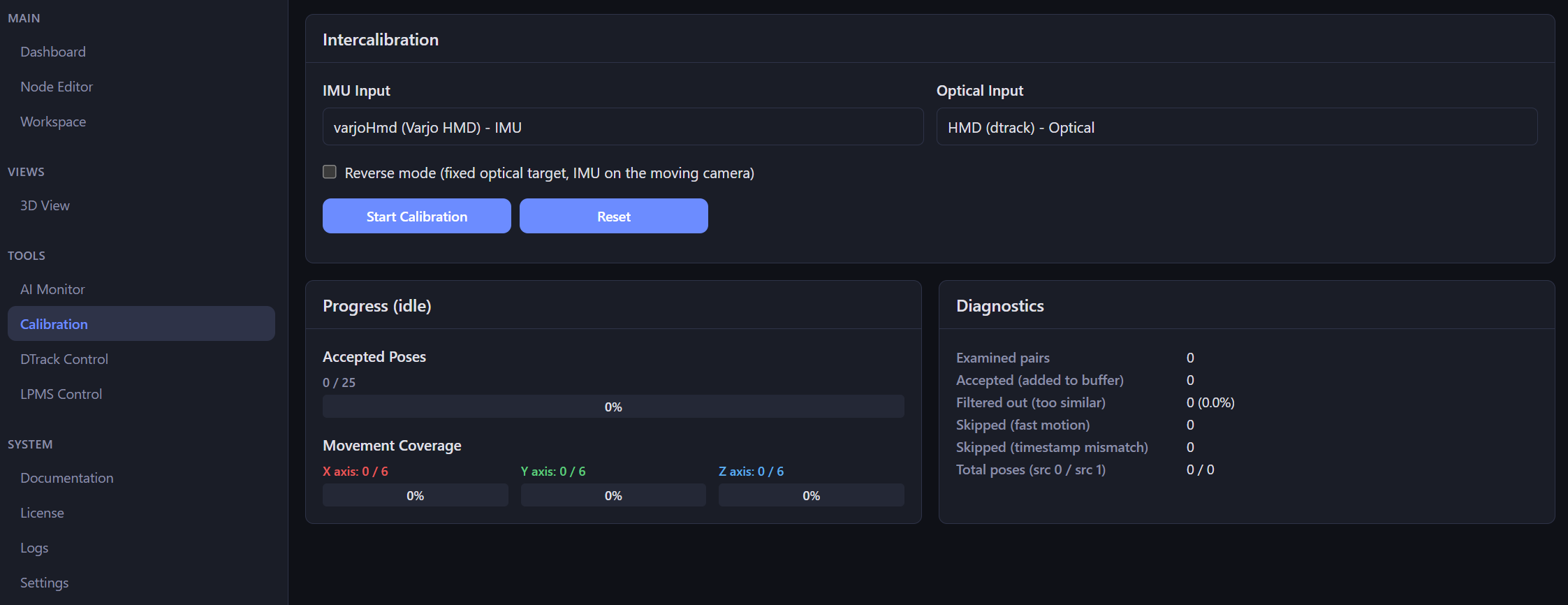
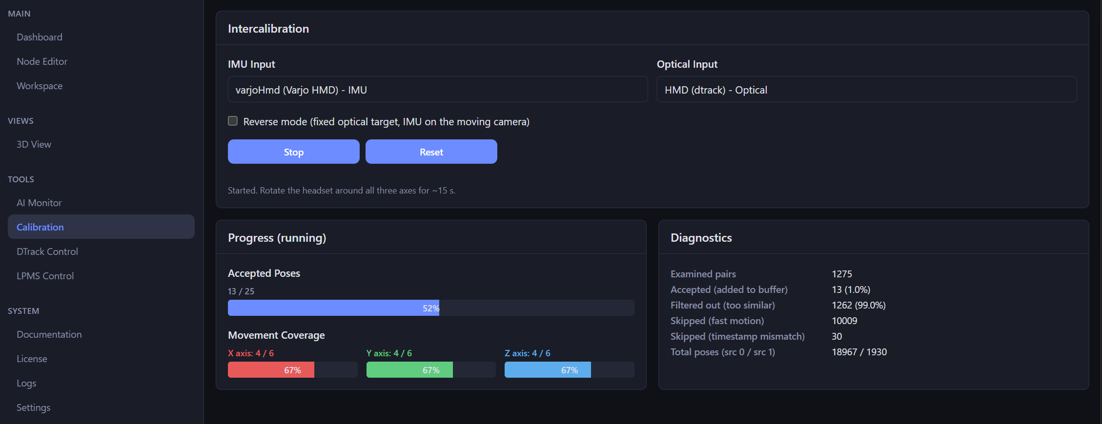
Reverse mode stays OFF for this setup. Reverse mode is only for a fixed optical target with the IMU on a separate moving camera; here the IMU and the optical marker are both rigidly attached to the same moving headset, which is the normal (non-reverse) case. The image below shows the Calibration page before starting the calibration.
Step by step in FusionHub
- Build the graph. Add and connect the four nodes above:
- DTrack Optical -> IMU-Optical Fusion (optical input)
- Varjo HMD -> IMU-Optical Fusion (IMU input)
- IMU-Optical Fusion -> Varjo HMD (FusedPose back, for rendering)
- DTrack Optical -> Intercalibration (Optical Input)
- Varjo HMD -> Intercalibration (IMU Input)
Set the Intercalibration type to IMU to Optical. Save the graph.
-
Bring up tracking. Start the measurement in the ART DTrack frontend and confirm the headset body is tracked and its data reaches the optical source node. Confirm the Varjo HMD bridge is receiving IMU.
-
Open the Calibration page. It mirrors the wired inputs. Confirm “IMU Input” and “Optical Input” both show a connected stream and not “Not connected”. If an input is missing, fix the wiring in the node editor first. The Start button stays disabled until both sides are ready.
-
Start Calibration. The page pushes the IMU-Optical settings to the filter and sends
start. The default acceptance gates are intentionally strict, so only deliberately slow, well-synchronized motion is used:
| Setting | Default | Meaning |
|---|---|---|
minNPoses | 25 | accepted pose pairs required before solving |
minPerAxisPoses | 6 | accepted pairs required per dominant rotation axis (forces three-axis coverage) |
minAngularDistance | 0.05 rad | a pair is only accepted if its orientation differs enough from the last accepted pair |
minNGoodPairs | 20 | minimum consistent pairs feeding the solver |
maxOmega | 0.15 rad/s (~8.6 deg/s) | drops IMU samples taken during fast motion; below natural head-turn speed, so only near-steady motion is accepted |
maxDelayMs | 5 | drops a pair when the IMU and optical timestamps disagree by more than this (tight sync) |
- Move the headset. Rotate the headset slowly and smoothly through a wide range of orientations, covering all three axes (look left/right, up/down, and tilt side to side). The solver needs diverse rotations to constrain the alignment; translation does not help. Keep motion gentle - anything faster than ~8.6 deg/s is rejected by the
maxOmegagate, and the goal is clean, near-steady samples that pair well between the two streams.
- Watch progress. The page shows:
- Accepted Poses (e.g. 0 / 25) - overall progress toward
minNPoses. - Movement Coverage per X / Y / Z axis (e.g. 0 / 6) - rotate until each axis bar fills. A stuck axis means you have not rotated around it enough.
- Diagnostics - examined vs accepted pairs, rejection rate, and skip counts (fast motion, timestamp mismatch). High “fast motion” skips mean you are moving too quickly; high “timestamp mismatch” means the two streams are not time-aligned.
- Convergence. When the gates are satisfied the solver runs, the filter flips to finished, and the Result card shows the recovered alignment quaternion (with roll/pitch/yaw) and an orientation gizmo previewing it against the identity frame. The result is frozen in a snapshot so it survives the engine rebuild. See an example of a completed calibration below.
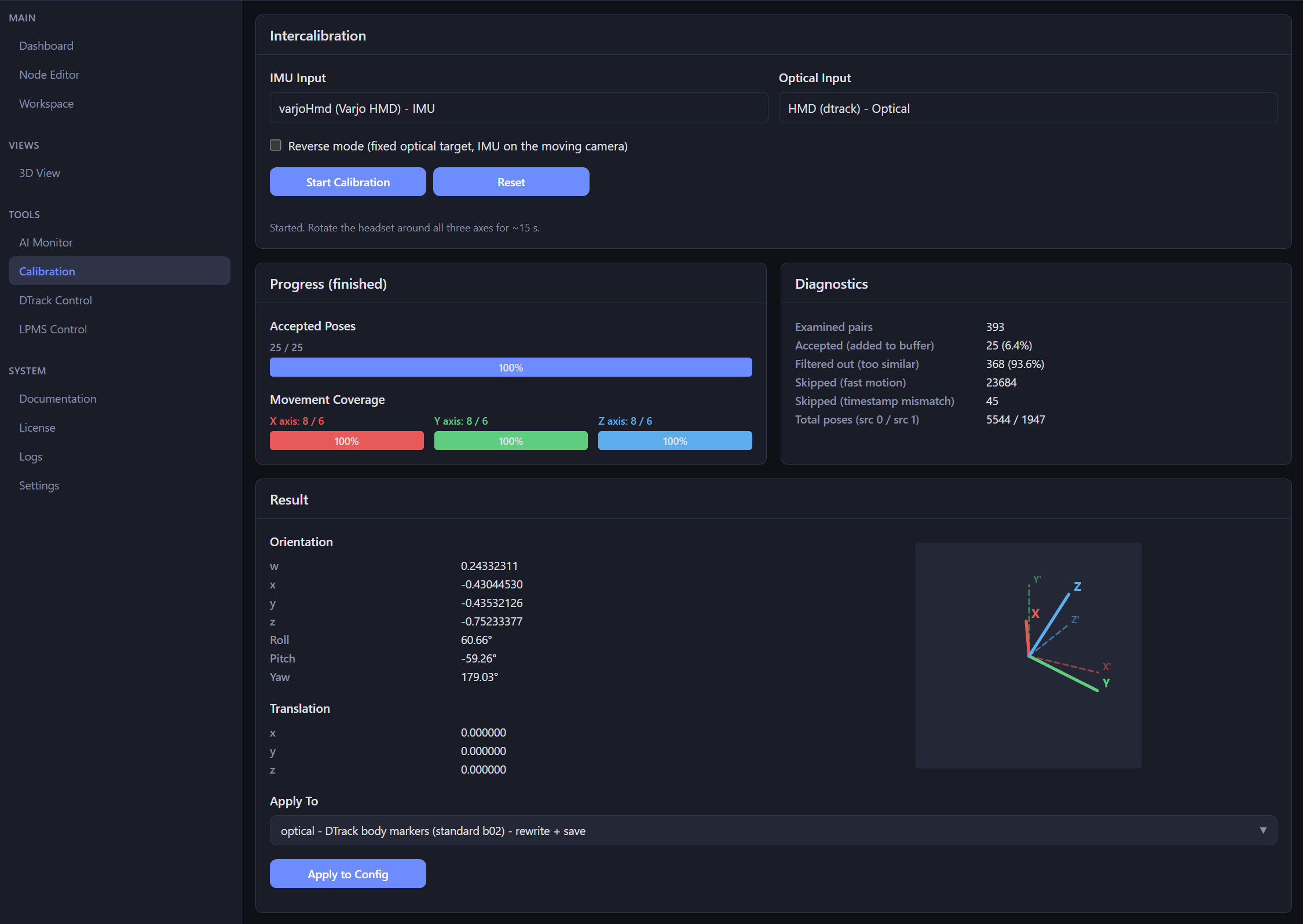
- Apply the result. In the Apply To dropdown pick the optical tracking body that corresponds to your HMD target. The result of the calibration will be applied to the body. If sucessful you should see a message like below in the status section:

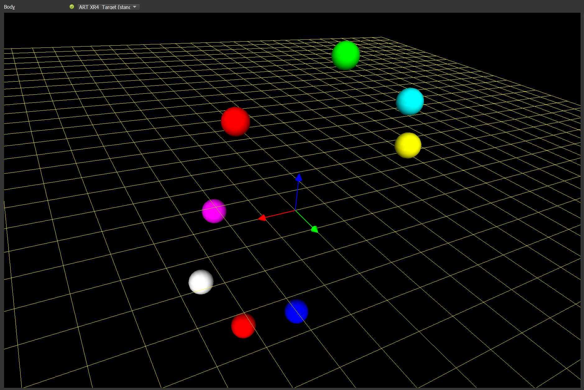
Marker target view in DTrack before the calibration: Body coordinate frame is not correctly aligned with the headset.
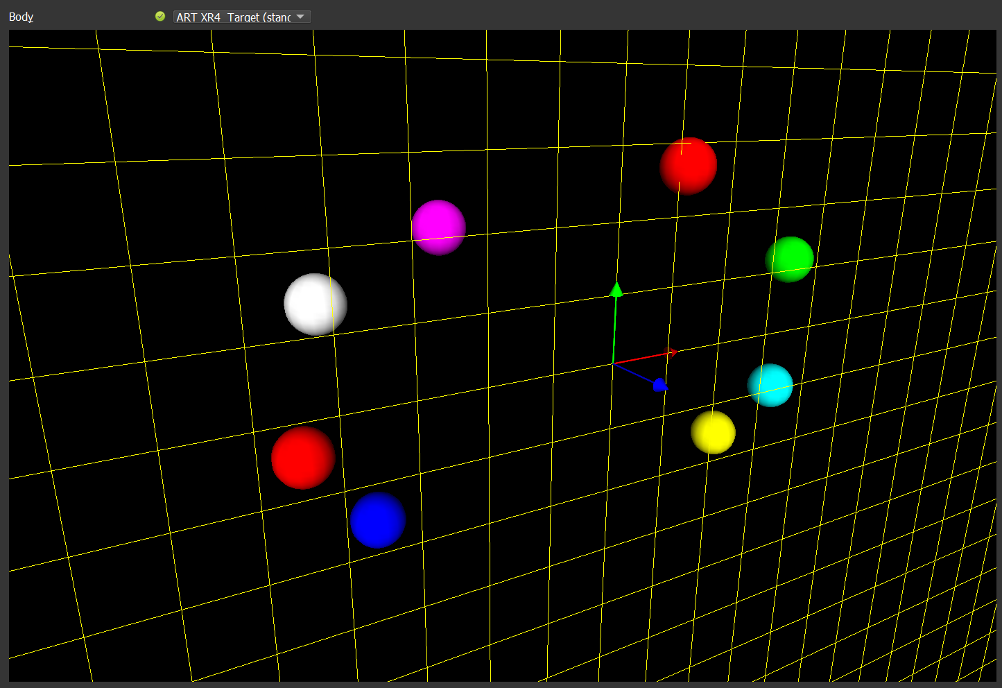
After calibration: Body coordinate frame is aligned with HMD.
- Verify. With the alignment applied, the IMU-Optical Fusion EKF emits a
single
FusedPosethat combines the optical system’s global, drift-free position/orientation with the IMU’s high-rate, low-latency motion. ThatFusedPoseroutes back into the Varjo HMD node and is published to the Varjo Base plugin for rendering (answeringvarjo_GetHMDPose). Move the headset around the volume and confirm the rendered pose is stable, globally referenced, and tracks the IMU’s fast motion without the pre-calibration misalignment.
Note on coordinate system convention: We normally use the SteamVR coordinate convention, X-right, Y-up, Z-back. If you’d like to use a different convention, you can adjust the axis assignment in the optical tracking node properties.
LPVR-DUO Reference IMU Alignment
In a moving vehicle the headset cannot be tracked against the world alone. The HMD’s own IMU measures orientation in inertial space, so inside a car it senses the sum of two motions: the wearer turning their head, and the car itself turning, accelerating, and moving over the road. For in-car VR the rendered scene must be stabilized to the cabin, not to the world, so the vehicle’s motion has to be removed from the headset’s signal.
LPVR-DUO does this with a reference IMU rigidly fixed to the tracking camera, which in turn is mounted in the car. Because the camera and the reference IMU form one rigid body that moves with the vehicle, the reference IMU measures the car’s motion directly. FusionHub’s Differential IMU node then subtracts the reference IMU’s angular velocity from the headset (primary) IMU’s angular velocity, leaving the head’s rotation relative to the cabin.
For that subtraction to be correct, the Differential IMU node needs the fixed rotation between the reference IMU frame and the camera’s optical frame. The Reference IMU Alignment calibration recovers exactly this rotation.
How it works
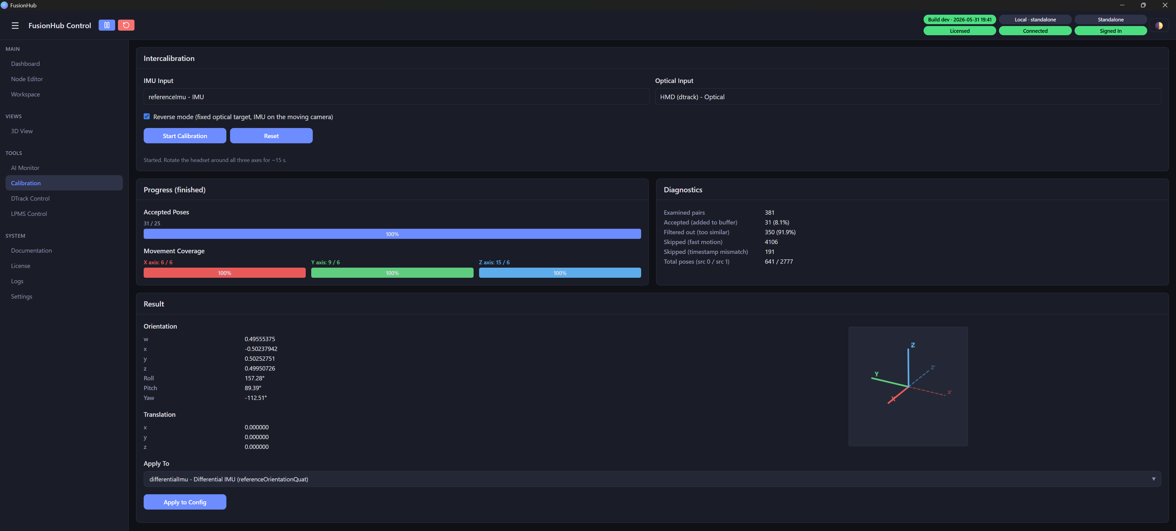
Unlike the headset calibration above, here the IMU is attached to the moving camera and the optical target stays still. This is the Reverse mode case of the IMU-Optical Intercalibration node: a fixed optical target with the IMU on a separate moving optical sensor.
Place an optical target stationary in the tracking volume and rotate the camera (with its attached reference IMU) slowly around it, covering all three axes. As the camera turns, the optical system sees the target’s orientation change while the reference IMU measures the same physical rotation in its own frame. The solver recovers the single fixed rotation that maps the reference IMU frame onto the camera’s optical frame. In Reverse mode the filter inverts the optical pose before feeding the solver, since it is the sensor that moves and the target that is fixed; the result is the rotation of the IMU relative to the camera optical frame.
The same acceptance gates as the headset calibration apply (slow, three-axis motion below ~8.6 deg/s, tight IMU/optical time sync), so move the camera gently and cover every axis until the per-axis coverage bars fill.
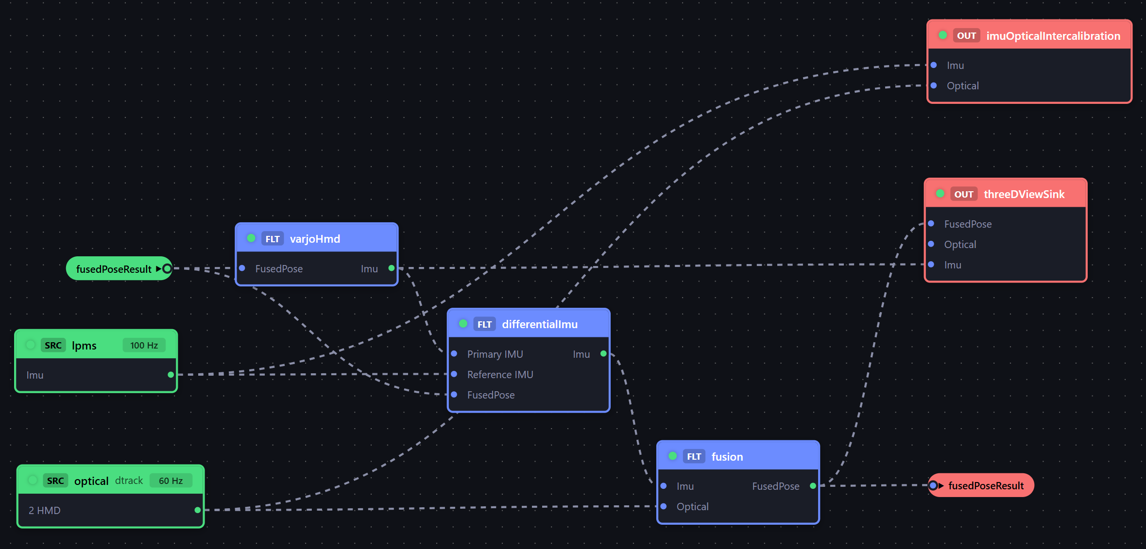
Applying and using the result
The recovered alignment is applied as the Differential IMU node’s reference-IMU-to-optical rotation. With it in place the node rotates the reference IMU’s angular velocity through the current headset orientation into the headset IMU frame and subtracts it from the headset gyroscope, emitting a vehicle-decoupled IMU stream:
- Primary IMU input - the headset IMU.
- Reference IMU input - the camera-mounted reference IMU.
- Output - the differential IMU stream, which feeds the headset’s pose fusion so the rendered orientation follows the head relative to the cabin, not the world.
Apple Vision Pro
The Apple Vision Pro is handled differently from the Varjo XR-4: instead of fusing a raw IMU stream, FusionHub works with the headset’s native inside-out (ARKit) tracking. The headset runs the ALVR client and streams to the PC, where the ALVR Bridge node receives the native pose (and IMU data) and sends the final fused pose back to the headset for rendering.
Inside-out tracking is smooth and high-rate, but only locally referenced: its origin is wherever the headset booted, and it can drift over time. The outside-in optical system - a DTrack-tracked marker body attached to the headset - provides the global, drift-free reference. The Inside-Out Fusion filter (license feature imu_optical_fusion) blends the two into a single globally referenced pose: motion follows the headset’s inside-out tracking while being pulled continuously onto the optical reference.
For that blend to be correct, the filter needs the rigid transform between the marker body frame and the headset’s inside-out frame. Both inputs are full 6-DOF poses, so this is a hand-eye calibration (the classic AX = XB problem): as the headset moves, both streams see the same physical motion in their own frames, and the solver recovers the fixed transform between them - rotation and translation, unlike the rotation-only IMU-optical case.
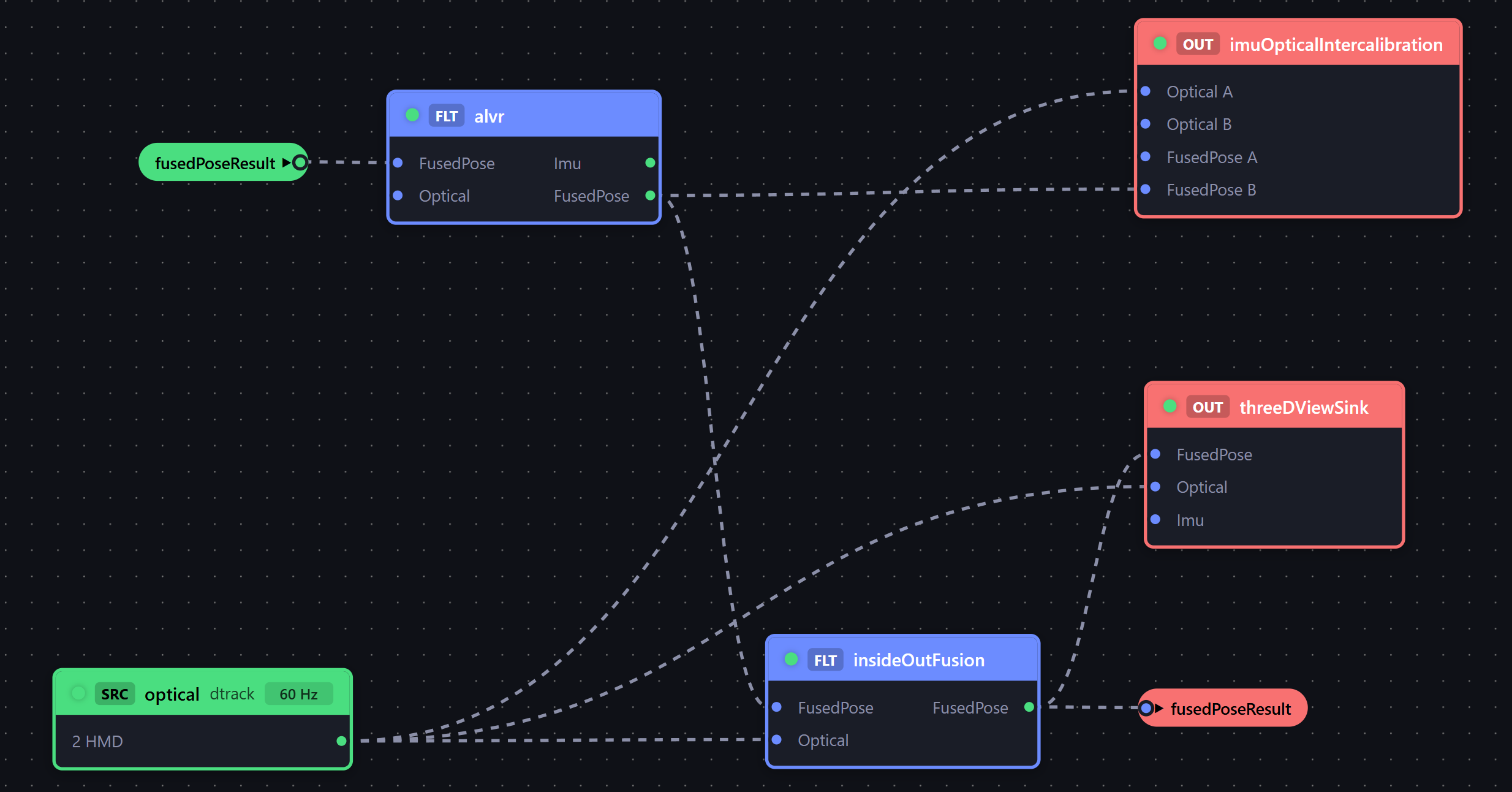
The graph above shows the complete Vision Pro arrangement:
- DTrack Optical source - streams the headset’s marker body (“HMD”)
- ALVR Bridge - connected to the headset; outputs the native pose as
FusedPose - Inside-Out Fusion - Optical input from DTrack, FusedPose input from the ALVR Bridge; its fused output routes back into the ALVR Bridge for rendering
- IMU-Optical Intercalibration with Calibration Type set to Hand-Eye (
handEye)
Wiring the calibration node
In handEye mode the Intercalibration node exposes pose-pair slots instead of an IMU slot: Optical A / B and FusedPose A / B. Wire the DTrack Optical stream to side A and the ALVR Bridge’s FusedPose output to side B. Since both sides are pose streams of the same motion, the Calibration page lists them explicitly as Pose Input A and Pose Input B so you can confirm which stream landed on which side.
Step by step
-
Bring up tracking. Start tracking of the headset body in the ART DTrack frontend, and connect the Vision Pro through ALVR (ALVR Control page) so the bridge receives the native pose.
-
Open the Calibration page. Confirm Pose Input A shows the DTrack optical stream and Pose Input B the ALVR Bridge FusedPose stream.
-
Start Calibration and rotate the headset slowly around all three axes, exactly as for the Varjo XR-4: the same acceptance gates apply (slow motion, three-axis coverage, tight time sync), and the page shows accepted poses, per-axis coverage bars and rejection diagnostics.
-
Result. When the solver converges, the Result card shows the recovered orientation (with roll/pitch/yaw) and translation - the rigid transform between the marker body and the headset’s native tracking frame.
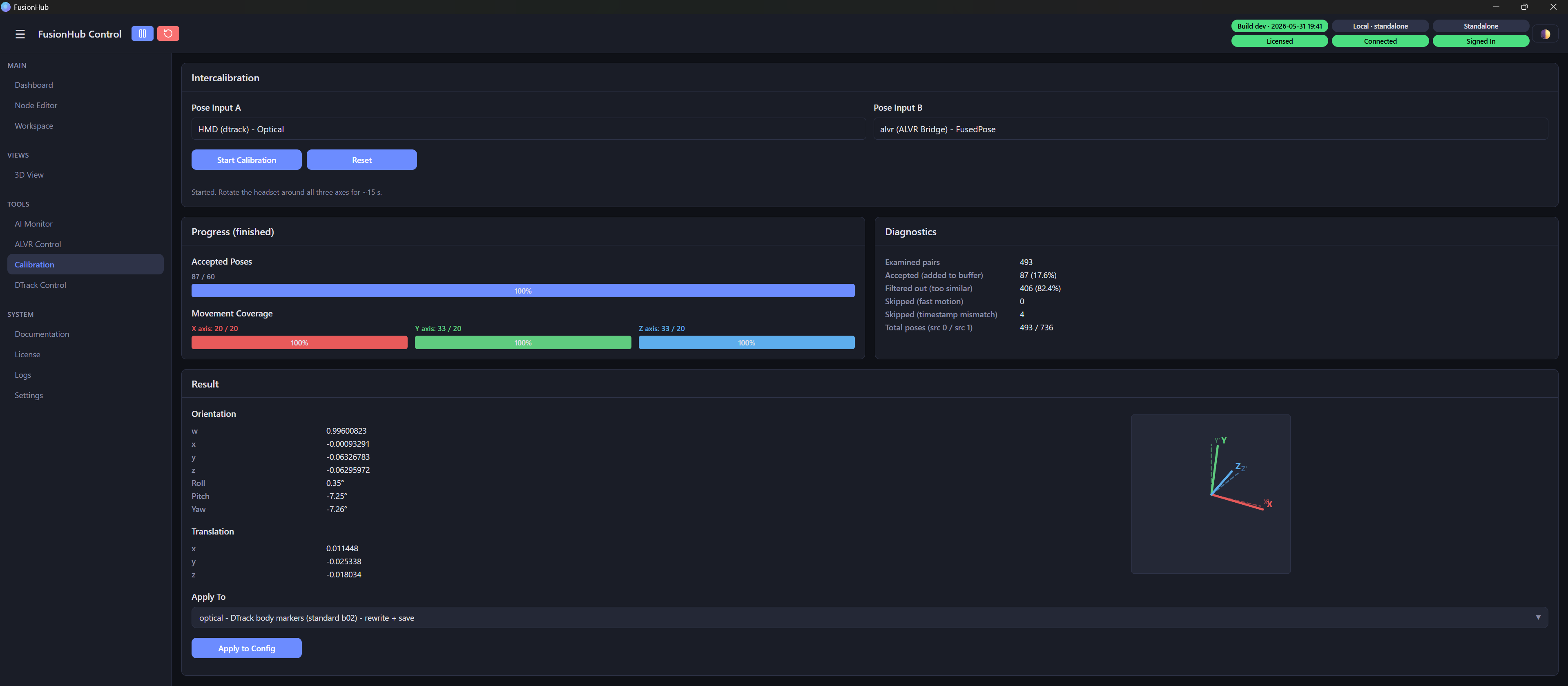
- Apply the result. In Apply To, two targets make sense:
- DTrack body markers (rewrite + save) - rotates the marker geometry on the ATC so the optical body frame matches the headset’s native frame. The previous geometry is archived as a
.txtfile and tracking re-acquires automatically. This writes the rotation only; the small remaining position offset is absorbed by the Inside-Out Fusion filter’s auto-calibration. - Inside-Out Fusion (opticalOrientationOffset / opticalPositionOffset) - writes rotation and translation into the filter as a static offset instead, leaving the body geometry untouched. This also switches the filter’s online auto-calibration off, so the fixed result is not chased away at runtime.
Press Apply to Config and confirm the success message in the status section.
- Verify. Walk and look around the tracking volume. The rendered scene should stay locked to the world (no drift accumulating over minutes), and there should be no jump when the optical system momentarily loses and re-acquires the marker body.
XREAL (Air 2 Ultra and One Pro)
XREAL glasses follow the same architecture as the Varjo XR-4: the glasses’ built-in IMU is the high-rate inertial source and the outside-in optical system provides the global reference. FusionHub reads the IMU directly over USB through the IMU Source node (driver type XREAL Air 2 Ultra or XREAL One Pro, ~1000 Hz), so no vendor runtime is required. The marker body is attached to the glasses and tracked by DTrack.
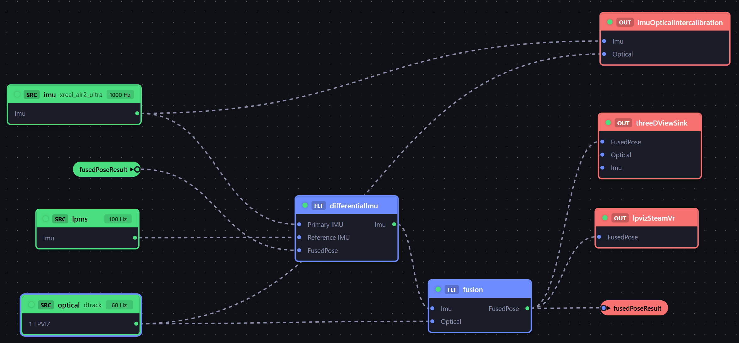
The graph above is the in-vehicle LPVR-DUO arrangement:
- IMU Source (XREAL driver) - the glasses’ IMU, used as the primary IMU
- LPMS Sensor - the vehicle-mounted reference IMU
- Differential IMU - subtracts the vehicle motion from the glasses’ IMU (see the LPVR-DUO Reference IMU Alignment section above)
- DTrack Optical source - streams the glasses’ marker body (“LPVIZ”)
- IMU-Optical Fusion - fuses the differential IMU with the optical body into the final pose
- LPVIZ SteamVR Output - publishes the fused pose to SteamVR for rendering
- IMU-Optical Intercalibration with Calibration Type set to IMU to Optical
For a static room setup without a vehicle, drop the LPMS and Differential IMU nodes and wire the XREAL IMU straight into the IMU-Optical Fusion filter; the calibration procedure is unchanged.
Calibration
This is the standard IMU-to-Optical calibration described in the Varjo XR-4 section - the same wiring, acceptance gates and motion pattern apply. Reverse mode stays OFF: the IMU and the marker body are both rigidly attached to the same moving glasses.
-
Bring up tracking. Start tracking of the glasses’ body in the ART DTrack frontend and confirm the XREAL IMU stream is alive (the IMU Source node shows its sample rate in the node editor).
-
Open the Calibration page. Confirm IMU Input shows the XREAL IMU stream and Optical Input the glasses’ DTrack body.
-
Start Calibration and rotate the glasses slowly around all three axes until the per-axis coverage bars fill. Keep the motion gentle - light glasses are easy to move too fast, and fast-motion samples are rejected (visible as a high “Skipped (fast motion)” count in the diagnostics).
-
Result. The solver recovers the rotation between the IMU frame and the optical body frame; the translation reads zero since the IMU-optical solve is orientation-only.
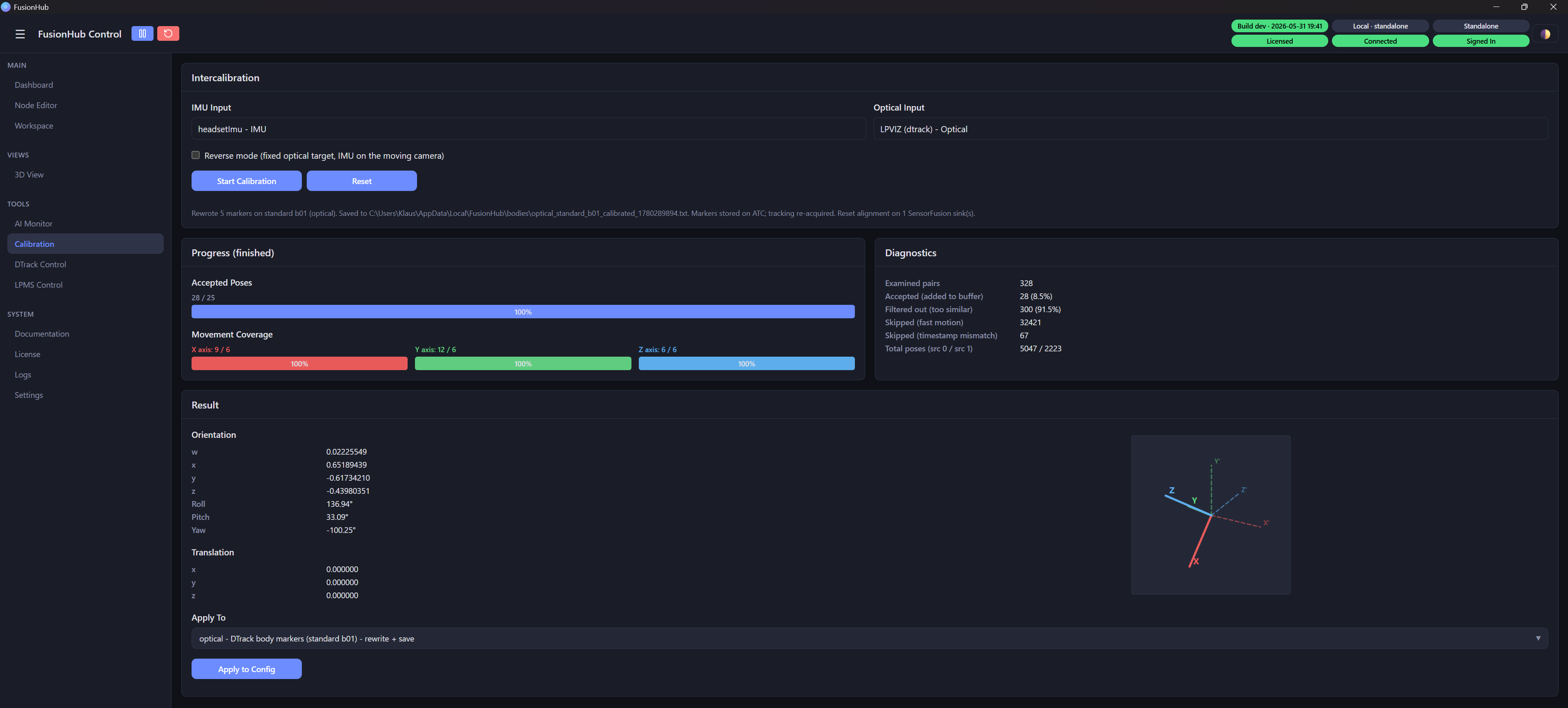
-
Apply the result. In Apply To pick the glasses’ DTrack body (rewrite + save) and press Apply to Config. The marker geometry is rewritten on the ATC so the body frame matches the glasses’ IMU frame, the previous geometry is archived as a
.txtfile, tracking re-acquires, and any alignment already stored in the fusion filter is reset to identity (the body now carries the alignment). Alternatively, apply to the fusion filter’s SensorFusion alignment to leave the body geometry untouched. -
Verify. Put the glasses on and move through the volume: the SteamVR-rendered view should rotate exactly with the head, with no tilt or lag between the IMU motion and the optically referenced orientation.