Point Calibration
Point calibration aligns the coordinate system of an outside-in optical tracking system (ART, OptiTrack) with a virtual reference frame by probing known real-world points with a tracked stylus. FusionHub solves the rigid transform between the two frames and writes it into the optical source, so every pose the source publishes afterwards is expressed directly in the virtual frame.
The typical use case is a mixed reality simulator: a cockpit with real screens, a real stick and throttle, and a video see-through headset such as the Varjo XR-4. The rendering engine draws the virtual world in the coordinate frame of the cockpit’s 3D model, while the tracking system reports poses in its own room frame, whose origin and orientation depend on how the cameras were calibrated. Point calibration closes that gap: after applying it, the headset pose that FusionHub delivers is in the cockpit model frame, and virtual overlays land exactly on the real screens and controls.
Besides aligning the whole tracking volume, the same node can calibrate a single tracked object against its own 3D model - see the “Calibrate a tracked object” section below.
Setup
Add a Point Calibration node to the graph and connect the optical source that tracks the stylus body to its Stylus input:
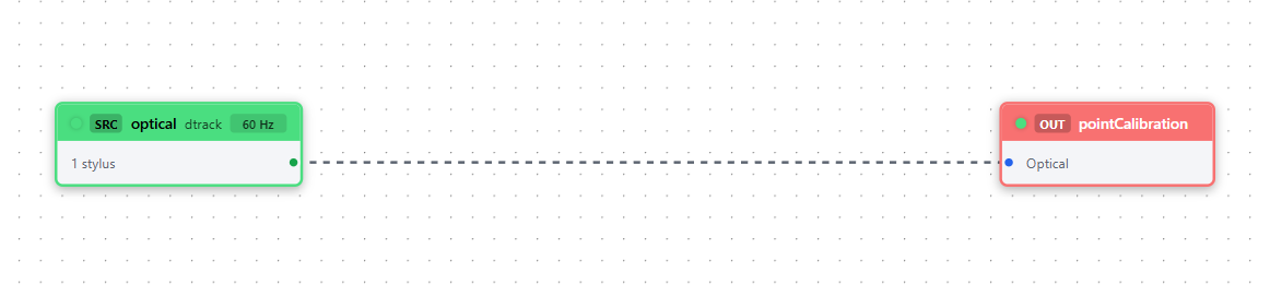
You need:
- An optical source streaming the stylus rigid body. For an ART system this is the DTrack optical source with the stylus body in its body list; verify on the DTrack Control page that the body shows “Tracked” while you hold the stylus in the tracking volume.
- A tracked stylus: any rigid marker body with a pointed tip works, for example a 3D-printed pointer with markers attached - the tip offset is calibrated in the first step below. An ART Measurement Tool can be used directly instead: add it under Measurement Tool IDs in the DTrack source settings and wire its
MToutput pin. Its reported position is already the calibrated tip, so Step 1 is skipped and the tip offset stays zero. - Virtual reference coordinates: the positions of at least three physical points of the cockpit, taken from its 3D model (screen corners, the base of the stick, a switch on a panel). The points must not lie on a single line, and accuracy improves when they are spread over all three axes.
With the node in the configuration, the Point Alignment page appears under Tools in the sidebar.
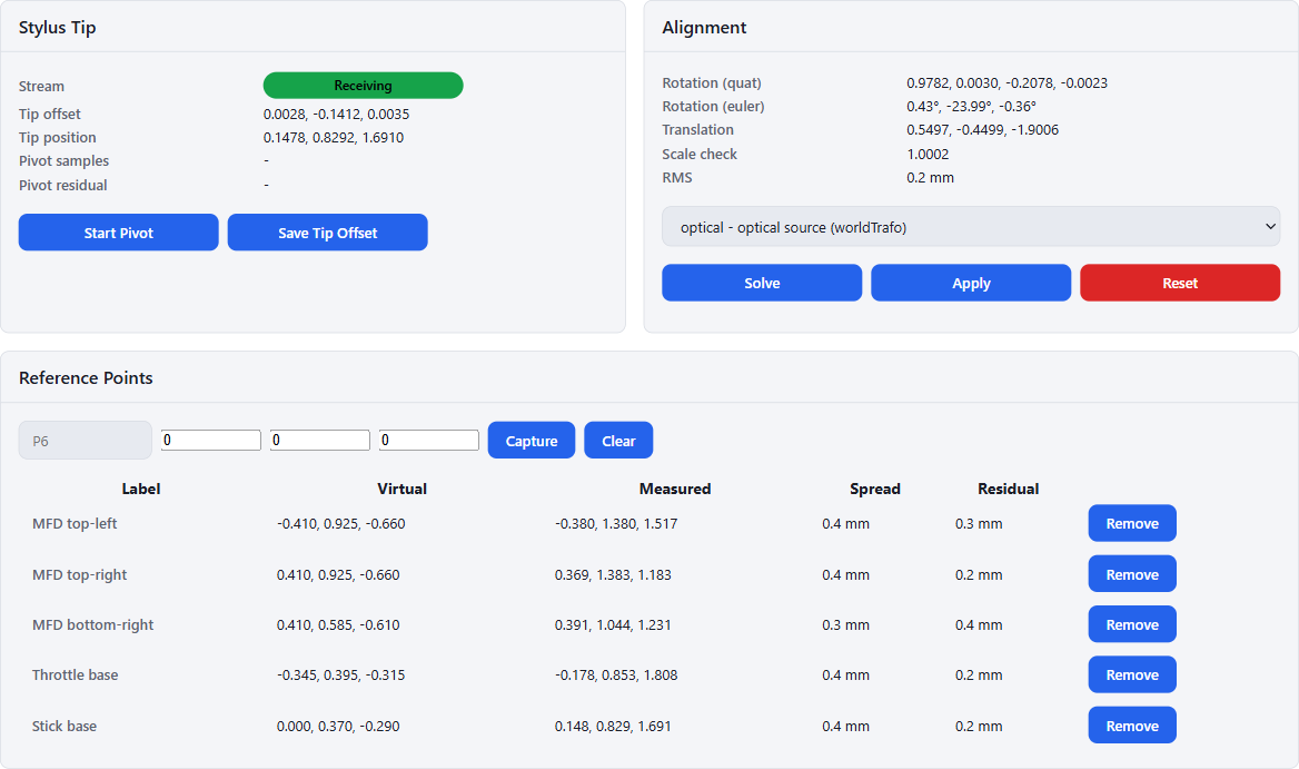
Step 1 - Calibrate the stylus tip
The tracking system reports the pose of the stylus marker body, not of its tip. The pivot calibration recovers the fixed offset from the body origin to the tip: place the tip in a small dent or corner so it cannot slide, press Start Pivot, and rotate the stylus around the resting tip - slow cones and twists around at least two different axes.
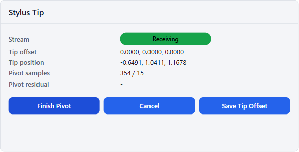
Press Finish Pivot when a few hundred samples have accumulated. The solved offset is shown in the Tip offset row and used immediately; Tip position now reads the tip location and should stay still while you rotate the stylus in place.
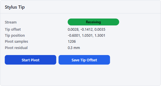
The Pivot residual is the RMS distance of the samples from the fitted pivot point - with a rigid stylus and clean tracking it should be around a millimeter or below. Press Save Tip Offset to persist the offset into the node’s configuration so it survives restarts; recalibrate only when the marker body is remounted.
With an ART Measurement Tool as the stylus, skip this step: the tracking system already reports the calibrated tip position, and the tip offset must stay at zero.
Step 2 - Capture the reference points
For each reference point: enter its label and virtual coordinates (meters, in the target frame), hold the stylus tip steadily on the corresponding physical point, and press Capture. The node averages the tip position over a short window and adds the pair to the table.
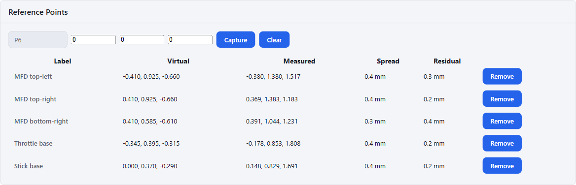
- Spread is the maximum deviation of the tip during the capture window. A few tenths of a millimeter means the stylus was held steady; centimeter-level values mean it moved - remove the point and capture it again.
- Three points are the minimum; four or five well-spread points make the solution noticeably more robust and give meaningful residuals.
Step 3 - Solve
Press Solve once all points are captured. The node computes the rigid transform (rotation + translation, Kabsch/Umeyama) that maps the measured points onto the virtual ones:

- Scale check solves for a uniform scale as a diagnostic. It must be very close to 1 - a clear deviation means the units of the virtual coordinates and the tracking system disagree (a warning is shown in that case).
- RMS and the per-point Residual column show how well the two point sets agree after alignment. Sub-millimeter values are typical for a careful capture with an ART system. One point with a much larger residual than the rest usually has wrong virtual coordinates - remove it, capture it again, and solve once more.
Step 4 - Apply
Choose the target in the dropdown and press Apply:
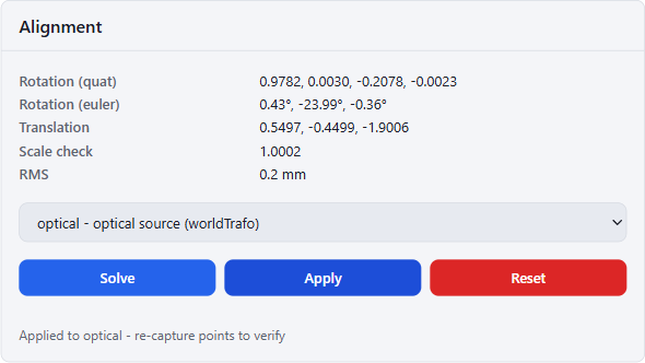
- Optical source (worldTrafo) writes the solved transform into the selected optical source’s world transform. The transform is composed with whatever world transform the source already applies (room directions/offset or a previous calibration), so applying a new solve replaces the effect of the old one instead of stacking on top of it. The engine restarts with the new configuration; from then on all bodies of that source - stylus, headset, any other tracked object - are published in the virtual frame.
- Download JSON saves the raw solution (quaternion, translation, scale, point pairs) for use in an external tool instead.
Verify
After applying, capture one of the reference points again: the Measured column should now match its virtual coordinates to within the capture noise.

If measured and virtual differ, check that the applied source is the one actually tracking the stylus, and repeat the capture with a freshly calibrated tip.
Calibrate a tracked object
The same node can align a single tracked body with its own reference frame - typically the CAD model of the object the markers are attached to. The marker set can be glued onto the object in any arbitrary way; the calibration finds where the object sits relative to its marker body and bakes the correction into the DTrack body itself, so the tracking system reports the object’s pose directly in the model frame afterwards. This mode requires an ART/DTrack system, because the body geometry is rewritten on the controller.
Calibrate the marker set as a body in DTrack as usual, then connect its optical stream to the node’s Target Body input, in addition to the stylus on the Stylus input:
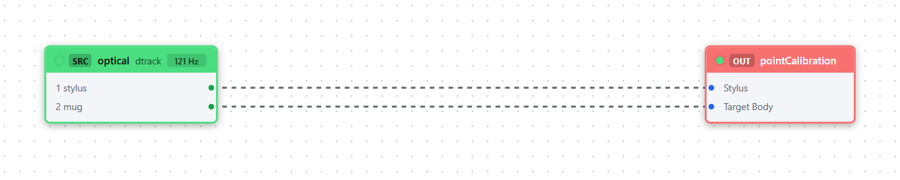
As soon as target body data arrives, the page switches to target-body mode: the Mode row reads “Target body” and a stream badge shows whether the body is currently tracked.
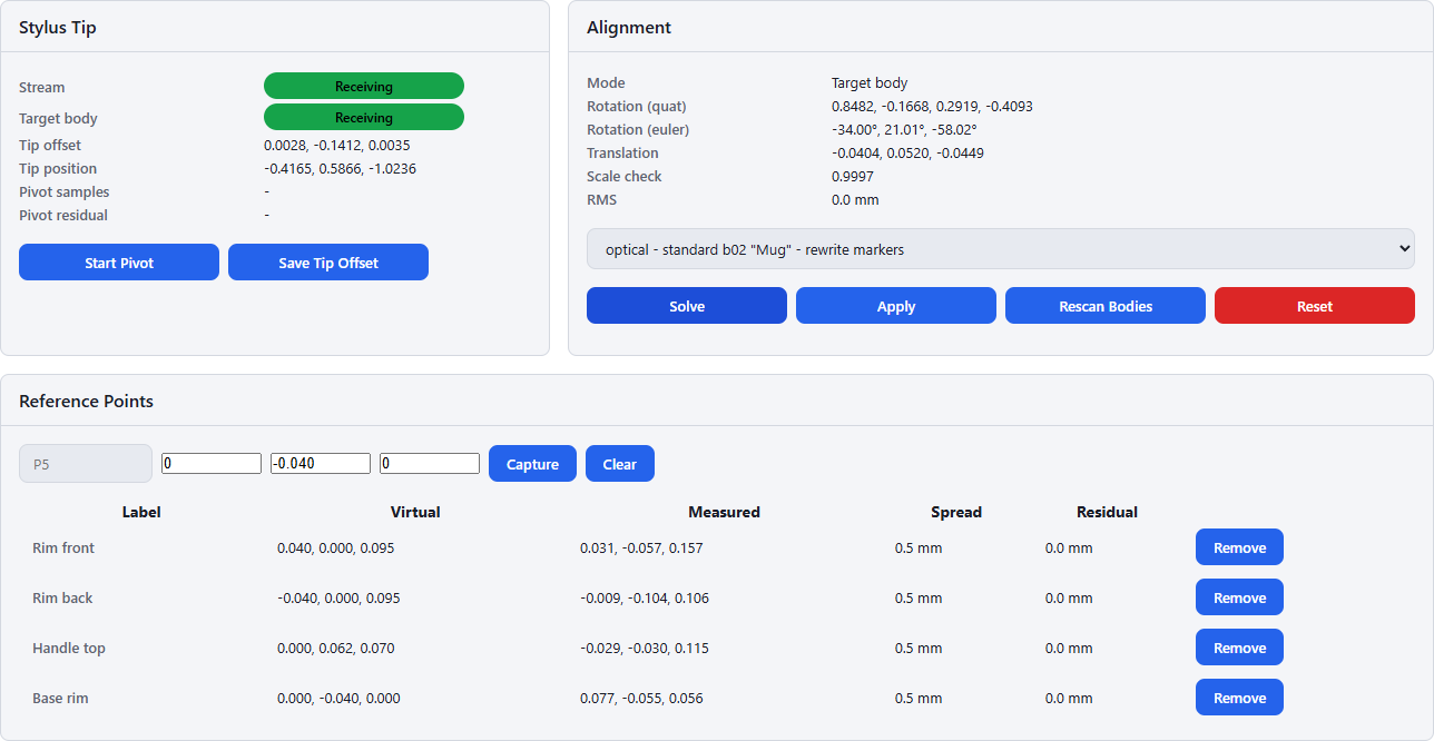
The workflow is the same as above, with three differences:
- The virtual coordinates are points of the object’s own model, for example CAD coordinates of corners, dimples, or hole centers. Pick features the stylus tip can rest on unambiguously; smooth freeform surfaces make poor reference points.
- Each captured tip position is stored relative to the tracked body rather than the room, so the object may be moved freely between captures - it only has to be tracked while a capture is running.
- Apply writes to the DTrack body instead of the source’s world transform. FusionHub reads the body’s marker positions from the controller, re-expresses them in the model frame, writes them back, and restarts the measurement so the body is re-acquired. The previous geometry is saved as a body file under
%LOCALAPPDATA%/fusionhub/bodies/on the machine running FusionHub. No FusionHub settings are changed - the corrected pose comes from the tracking system itself and reaches every consumer.
The apply dropdown lists the calibrated bodies found on the controller, with the body wired into the Target Body input preselected; press Rescan Bodies after changing the controller configuration. The controller must be reachable and not exclusively held by another client - close the DTrack frontend if the apply reports restricted access.
After a successful apply the captured points are cleared. To verify, capture one of the model points again: Measured is now expressed in the object’s model frame and should match the entered coordinates to within the capture noise.
Use with an HMD
Point calibration handles the world side of a mixed reality setup - where the tracking frame sits relative to the virtual scene. The headset itself additionally needs the IMU-to-optical alignment described in the Headset Calibration Tutorials, which relates the marker body on the headset to its internal sensors. The two calibrations are independent: run the point calibration whenever the camera setup or the physical cockpit moves, and the headset calibration when the marker body on the headset is remounted.