Optical See-Through Calibration
An optical see-through headset draws its image on a transparent display in front of the eye, so the virtual content is only registered with the real world if FusionHub knows exactly where the user’s eyes are and how the display projects onto them. Unlike a video see-through headset, there is no camera image to align against and no factory-calibrated relationship between the display and the wearer: the per-eye field of view, the interpupillary distance, and the position of the eyes relative to the tracked marker body all differ from user to user and from mounting to mounting.
OST calibration measures them. It follows the classic SPAAM procedure: a crosshair is shown at a known pixel position on the display, the user moves a tracked stylus until its tip visually coincides with that crosshair, and the pair (pixel, 3D tip position in the headset frame) is recorded. Each pair constrains the ray that leaves the eye through that pixel; enough pairs at different image positions and different distances determine the whole projection. FusionHub solves for the per-eye frustum, the IPD, and the eye position, and writes the result into the LPVIZ display driver.
The result is a display model for one headset and one wearer. The frustum shape belongs to the headset, the IPD and eye position to the person, so a headset shared between users is best recalibrated per user - or at least given each user’s measured IPD.
Setup
Add an OST Calibration node to the graph and connect the optical source that tracks the stylus body to its Stylus input, and the optical stream of the headset’s own marker body to its HMD Optical input:

You need:
- A working LPVIZ setup: the display driver installed, the headset running as a SteamVR display, and an LPVIZ SteamVR Output node fed by the fusion result. The calibration reads the display resolution from the driver’s settings and writes its result back there.
- A tracked headset body. Wire the raw optical stream to HMD Optical rather than the fused pose. Raw optical frames stop arriving the moment the tracking system loses the body, so a capture taken during a dropout fails loudly instead of silently pairing the stylus against a frozen pose - the fusion output keeps re-emitting the last optical sample at IMU rate and looks perfectly alive while doing so. The HMD Pose input accepts a
FusedPoseas a fallback when no raw stream is available. - A tracked stylus, exactly as for Point Calibration: any rigid marker body with a pointed tip, or an ART Measurement Tool whose reported position is already the calibrated tip.
- A headset body whose axes are the head axes, if you want to use the default solve mode. See “How the tracked body is interpreted” below.
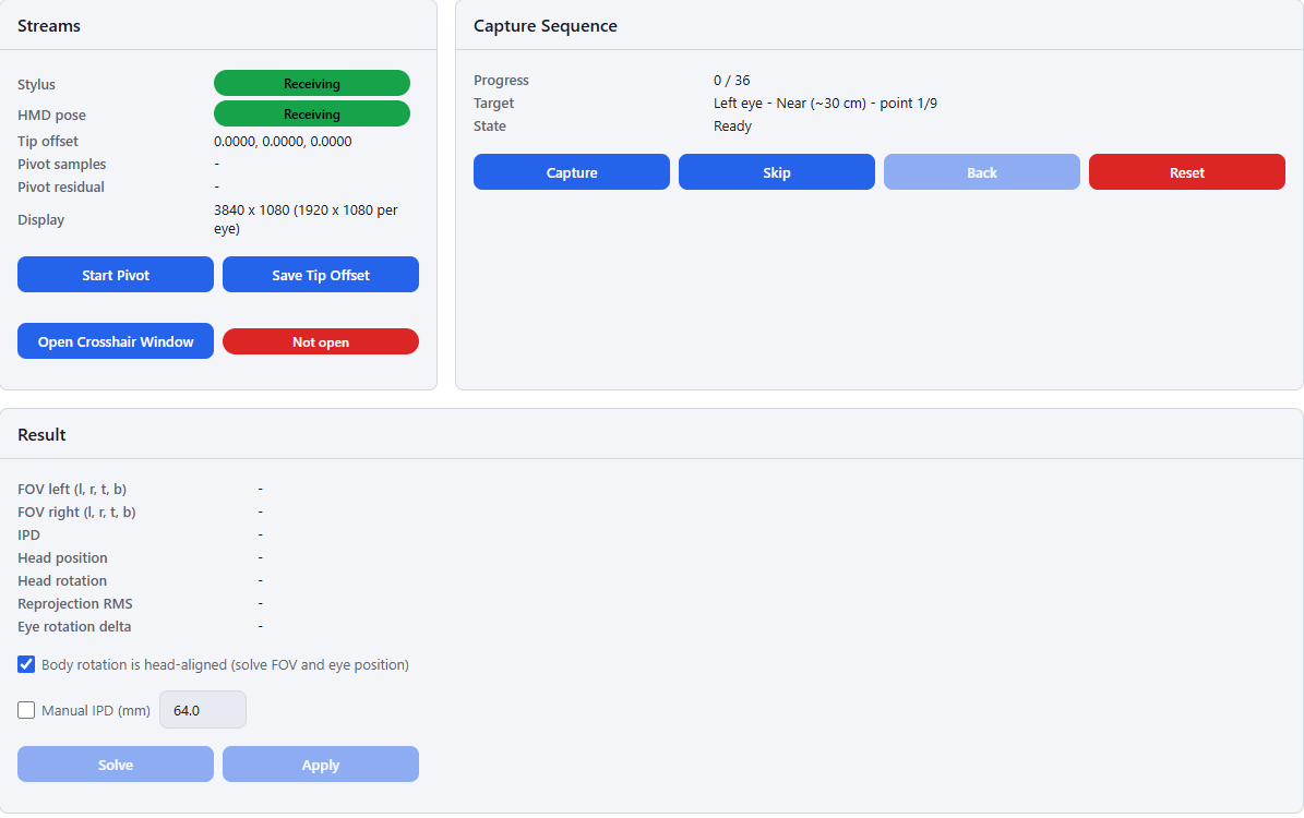
With the node in the configuration, the Display Alignment page appears under Calibration in the sidebar. The Streams card must show “Receiving” for both the stylus and the HMD pose before anything else works.
How the tracked body is interpreted
The solve has to relate the display to the tracked marker body on the headset, and there are two ways to run it, selected by the Body rotation is head-aligned checkbox in the Result card.
Checked (default). The marker body’s orientation is assumed to be the head orientation, so only the field of view and the position of the eyes relative to the body origin are unknown. This is the right mode when the headset body has been aligned with the headset’s own model - for example with the tracked-object mode of Point Calibration, which rewrites the DTrack body so its pose is reported in the model frame. The solve is then a small, well-conditioned fit and tolerates considerably more capture noise.
Unchecked. The full SPAAM solve additionally recovers the rotation between the display and the marker body, which is necessary when markers were glued on in an arbitrary orientation. It has more freedom and therefore needs a cleaner, better-spread capture to converge to something sensible.
Step 1 - Calibrate the stylus tip
The tracking system reports the pose of the stylus marker body, not of its tip, and the tip is what the user aligns with the crosshair. Place the tip in a small dent or corner so it cannot slide, press Start Pivot, and rotate the stylus around the resting tip in slow cones and twists around at least two axes. Press Finish Pivot once a few hundred samples have accumulated.
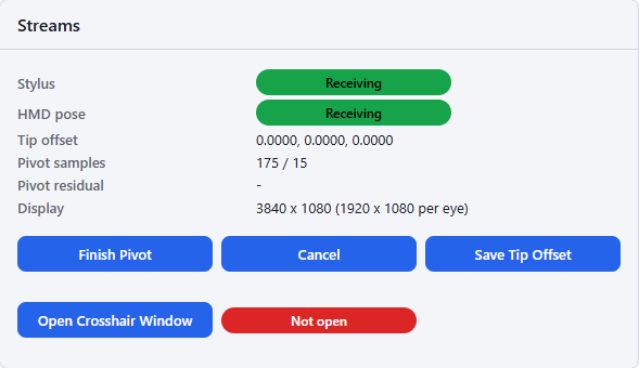
The Pivot residual is the RMS distance of the samples from the fitted pivot point; with a rigid stylus and clean tracking it should be around a millimeter or below. Press Save Tip Offset to persist the offset into the node’s configuration - do this before capturing samples, since saving rebuilds the engine and clears the session.
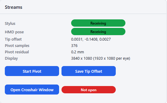
With an ART Measurement Tool as the stylus this step is skipped and the tip offset stays at zero.
Step 2 - Put the crosshair on the display
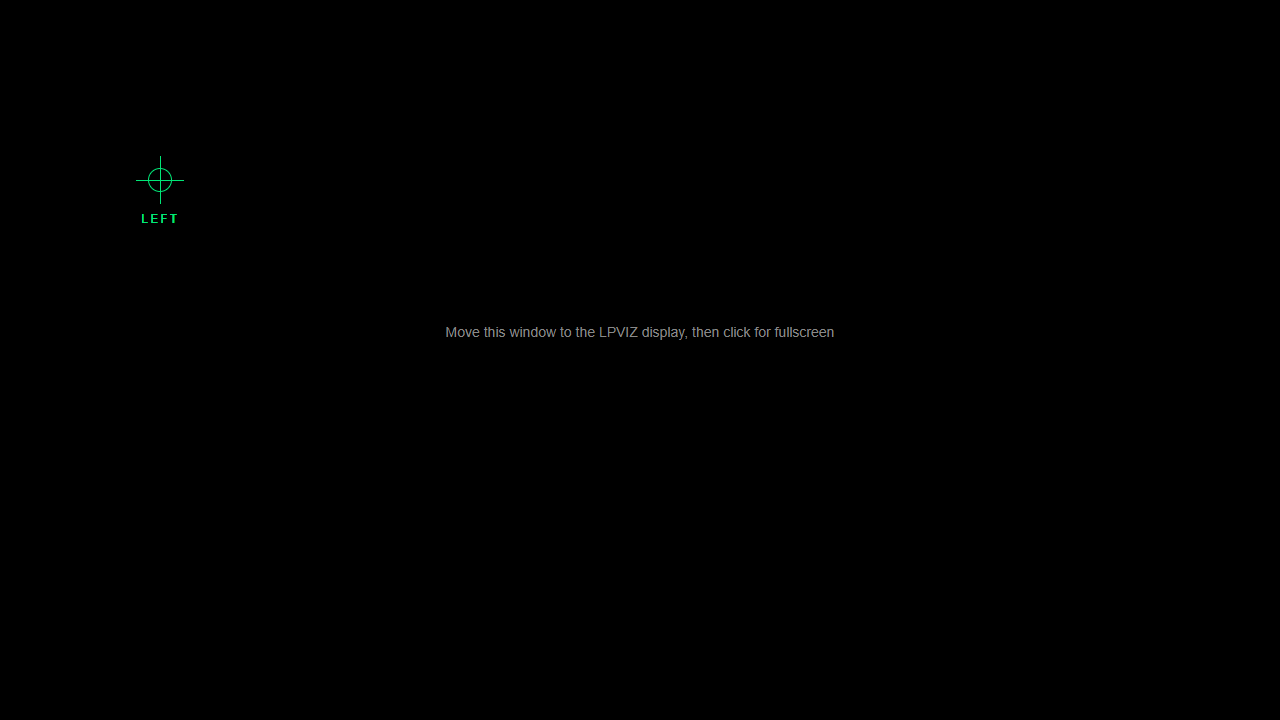
Press Open Crosshair Window, drag the window onto the LPVIZ display, and click it once to go fullscreen. The badge next to the button switches to “Connected” as soon as the window reports in.
The page is black with a single reticle. Black pixels emit no light on an additive see-through display, so in the headset only the reticle is visible, floating in the real world. It is green when idle and turns yellow while a capture is running. The pixel mapping is exact only when the window is fullscreen on the LPVIZ display - a windowed or half-covered crosshair produces a systematically wrong calibration.
The Display row in the Streams card shows the resolution the calibration assumes, taken from the driver settings, together with the per-eye viewport (a 3840 x 1080 side-by-side panel gives 1920 x 1080 per eye).
Step 3 - Capture the alignment sequence
The sequence has 36 steps: both eyes, two distances per eye, and a 3 x 3 grid of crosshair positions at 25%, 50% and 75% of the viewport in each direction. The Capture Sequence card shows which one is active - eye, pass, and point number.
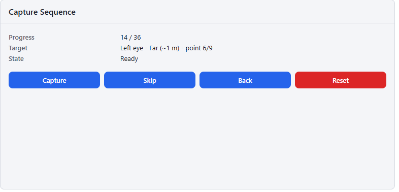
For each step:
- Close the eye that is not being calibrated. Only the half of the panel belonging to the active eye carries the reticle.
- Hold the stylus so that the tip visually sits in the center of the crosshair, at roughly the distance the pass asks for (~30 cm for the near pass, ~1 m for the far pass).
- Press Capture and hold both the stylus and your head still for the length of the capture window (750 ms).
A successful capture appends a row to the Samples table and advances to the next step automatically. A rejected capture leaves the step unchanged and prints the reason:
- “tip moved N mm during the window” - the tip wandered more than 10 mm relative to the headset. Since the tip is measured in the headset’s frame, head motion counts just as much as hand motion.
- “capture collected only N paired frames” - the stylus and headset poses could not be paired. A stylus frame is only paired with a headset pose younger than 200 ms, so this is the expected failure when the headset body is not tracked at that moment.
Skip and Back move through the sequence without capturing, Reset discards all samples and starts over.
The two distances matter. Alignments taken at a single distance lie on a plane, and neither the eye position nor the IPD is observable from them - the solve either fails or returns a plausible-looking but meaningless result. Spreading the near and far passes further apart (30 cm and 1 m rather than 40 cm and 80 cm) noticeably improves the fit.
Accuracy is limited by how precisely a human can hold a tip on a crosshair while an unfocused reticle floats at the display’s virtual image distance. About 5 mm of alignment noise at 40 cm is already 0.7°, which is the dominant error term in the result below - so it is worth taking the sequence slowly, bracing the elbow, and repeating steps that felt uncertain.
Step 4 - Solve
Solve becomes available once at least six samples exist for each eye; a complete 36-point sequence gives 18 per eye. Tick Manual IPD and enter the user’s measured interpupillary distance when it is known - it pins the one parameter that is only weakly observable from the capture, and an assumed 64 mm that is wrong by a few millimeters shows up later as a depth-dependent registration error.
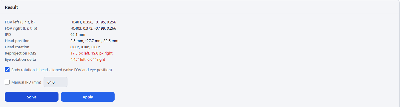
The Result card reports:
- FOV left / FOV right are the frustum edge tangents (left, right, top, bottom) at unit distance, not angles. The two eyes should be near mirror images of each other, and the horizontal spans should agree with the headset’s nominal values to within a few percent.
- IPD should land within a few millimeters of the user’s real IPD.
- Head position is the offset from the tracked body origin to the mid-eye point. Values of a few centimeters are normal; an anchor sitting above and in front of the eyes is typical.
- Reprojection RMS is how well the solved model reproduces the captured alignments. The value is highlighted above 10 px; careful captures with a hand-held stylus typically land around 20 to 30 px, which corresponds to well under a degree and is still usable. Values in the hundreds mean the capture is unusable.
- Eye rotation delta measures how far an unconstrained per-eye fit is from the head-aligned assumption. It is a diagnostic only: large values point at a marker body whose axes are not head-aligned, or at noisy samples. It reads “-” when the samples are too degenerate for the diagnostic fit to run.
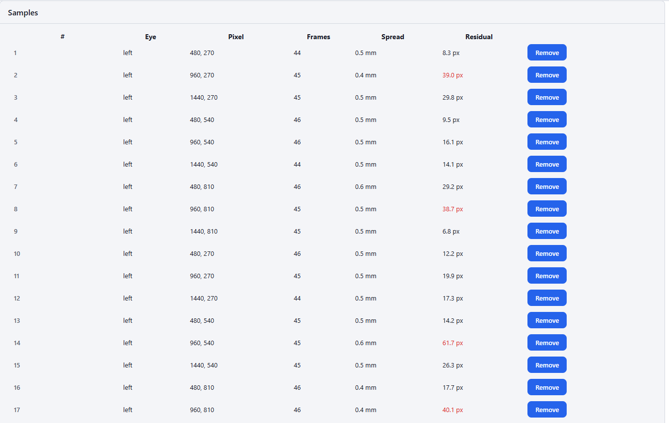
The Samples table lists each alignment with the number of frames averaged, the spread during the capture window, and its Residual after the solve. Residuals above 30 px are highlighted. The workflow that converges is: solve, remove the highlighted rows, solve again. One or two bad alignments out of 36 are enough to tilt the whole fit, and they are usually obvious in that column.
If the solve reports “a sample lies behind the display plane” or “solved focal length is negative”, the capture is geometrically inconsistent - most often a wrong or uncalibrated tip offset, or crosshair pixels that did not match what was on screen because the crosshair window was not fullscreen.
Step 5 - Apply
Apply writes the per-eye FOV, the IPD, and the head-to-tracker pose into the LPVIZ driver’s settings file. The driver reads that file at startup only, so SteamVR must be restarted before anything changes in the headset.
The same values are visible and editable afterwards in the LPVIZ node’s properties panel, which also carries the manual scale nudge described below. The panel’s preset “Reset to defaults” restores the shipped display model. Saving an LPVIZ preset captures the applied display model along with the node settings, so a calibrated user profile can be stored and restored as a preset.
Verify on the headset
Put the headset on, restart SteamVR, and look at a virtual object placed on a known real surface. Then move, and watch how the registration fails - the way it slips identifies which part of the model is off:
- Edges slip when you rotate your head, and come back when you stop. The field of view is off. Content that drags along with the head rotation means the tangents are too large; nudge the FOV down by a percent at a time with the scale buttons in the LPVIZ panel, save, and restart SteamVR.
- Objects shift when you translate your head, with the error fading as you look further away. The eye position is off, most often in depth. Re-run the calibration with a wider spread between the near and far pass.
- The error grows as you walk away from the tracking cameras. That is the tracking volume calibration, not the display model. No FOV or eye position will fix it - recalibrate the tracking system.
- Everything is uniformly offset, but stable. Check the marker body on the headset and the IMU-to-optical alignment described in the Headset Calibration Tutorials.
A residual vertical offset that survives an otherwise clean solve can be real: birdbath optics are mounted with a slight inclination, and that shows up as a shift of the vertical frustum center rather than as a fit error.
Relationship to the other calibrations
Three calibrations sit on top of each other in an optical see-through setup, and they are independent:
- Point Calibration aligns the tracking system’s coordinate frame with the virtual scene, and can align a marker body with the model of the object it is attached to. Run it when the cameras or the room setup change.
- Headset calibration relates the marker body on the headset to its internal IMU. Run it when the marker body is remounted.
- OST calibration relates the display to the eyes of the person wearing it. Run it per user, and after any change to how the headset sits on the head.