LPVR-DUO with Varjo Headsets
LPVR-DUO tracks a Varjo headset on a moving platform: a car, a truck cabin, a boat or a motion simulator. In a moving vehicle the headset IMU senses the vehicle’s turns as well as the head motion. LPVR-DUO adds a platform IMU that is fixed to the vehicle and subtracts its rotation from the headset IMU, so VR and AR content stays fixed to the vehicle while you drive.
With the standard LPVR-DUO package, an ART headset target and the LPMS-IG1 mounted in the slide holder, no calibration is needed: mount the hardware, load the configuration, start Varjo Base. The calibrations at the end of this page are only for custom setups.
The static (room) setup for the same headset is described in the Varjo XR-4 section of Using Headsets with FusionHub. Installing FusionHub and activating a license is described in Getting Started.
Components
| Component | Role | Connection to the FusionHub PC |
|---|---|---|
| Varjo headset (e.g. XR-4) with ART headset target | Headset IMU and display | Varjo headset cable, Varjo Base |
| ART SmartTrack 3 | Optical tracking of the headset target inside the vehicle | Ethernet |
| LPMS-IG1 with slide holder | Platform IMU, mounted on top of the SmartTrack 3 | USB |
| Windows PC | Runs Varjo Base, DTrack and FusionHub | - |
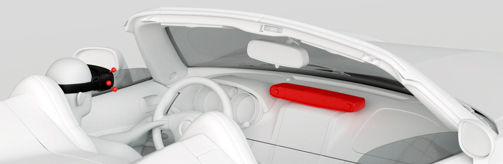
The SmartTrack 3 is mounted in the vehicle facing the driver, typically on the dashboard, so that the headset target stays inside its tracking volume.
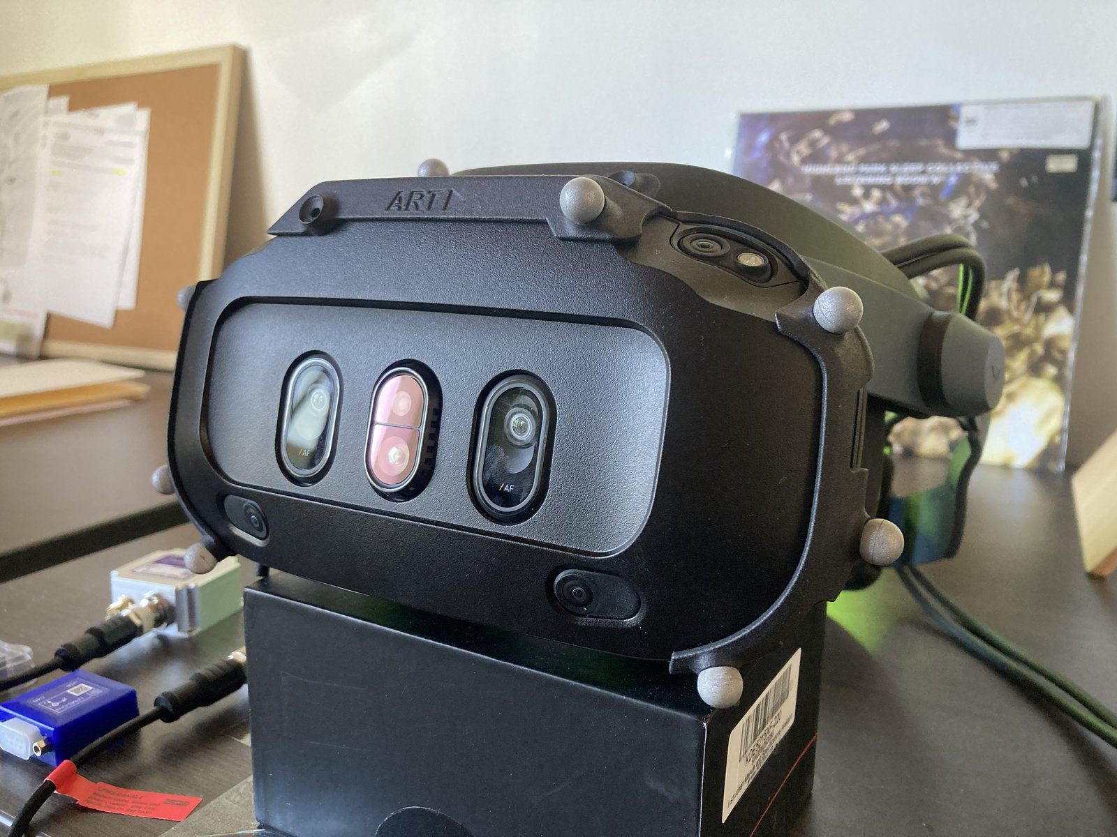
Attach the ART headset target to the headset. DTrack recognizes ART-made headset targets automatically, so the target is ready to use once it is calibrated as a body in DTrack, as shown in the Varjo XR-4 section of Using Headsets with FusionHub.
Mounting the platform IMU on the SmartTrack
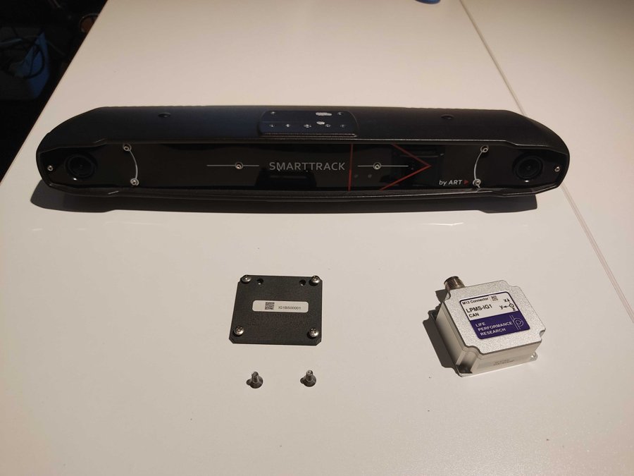
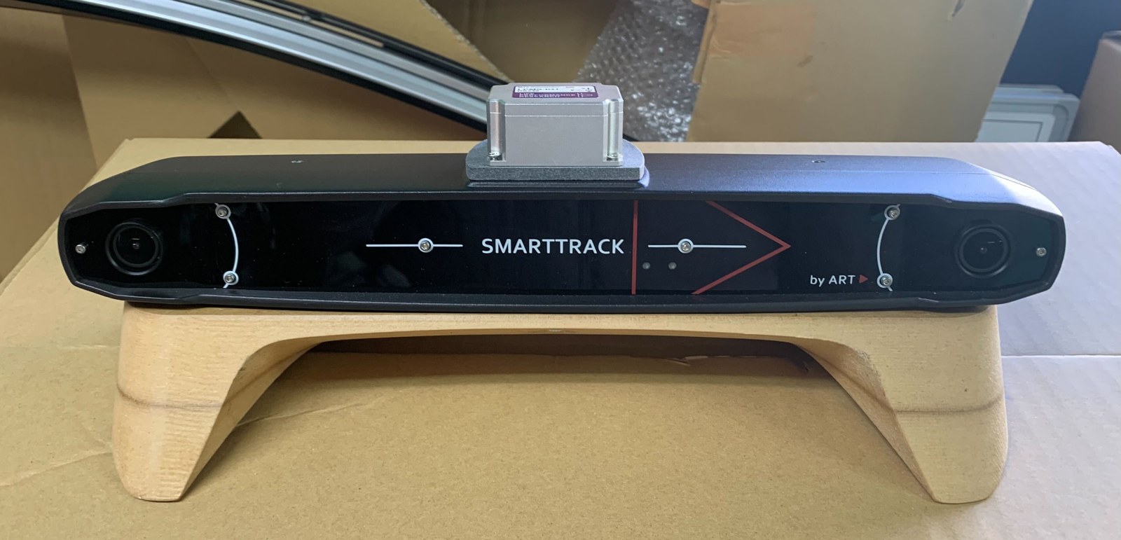
The slide holder mounts the LPMS-IG1 on top of the SmartTrack 3. Camera and IMU then form one rigid unit that can be installed in the vehicle as a whole. You need the SmartTrack 3, the slide holder with its four round-head screws, two countersunk screws, the LPMS-IG1 and a Phillips screwdriver.
- Screw the two countersunk screws loosely into the screw holes on top of the SmartTrack, leaving space under the heads for the holder. Remove any covers from the neighbouring screw holes so the holder sits flat.
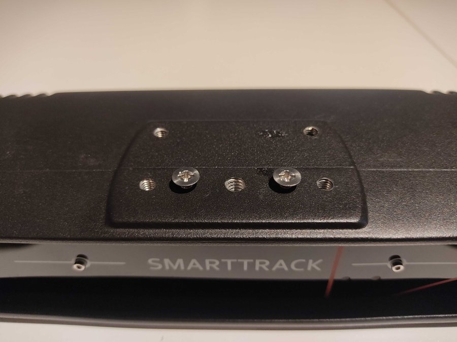
- Hold the slide holder with its wide keyhole openings over the screw heads, then push it towards the back of the SmartTrack until it locks in position. If it does not slide freely, loosen the screws a little more. Then tighten the two countersunk screws.
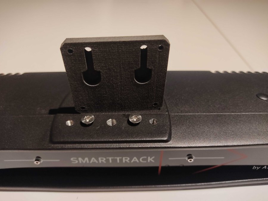
- Place the LPMS-IG1 on the holder with its M12 connector pointing towards the back of the SmartTrack and fix it with the four corner screws. This orientation matches the Reference Orientation stored in the LPVR-DUO configuration, so no calibration is needed.
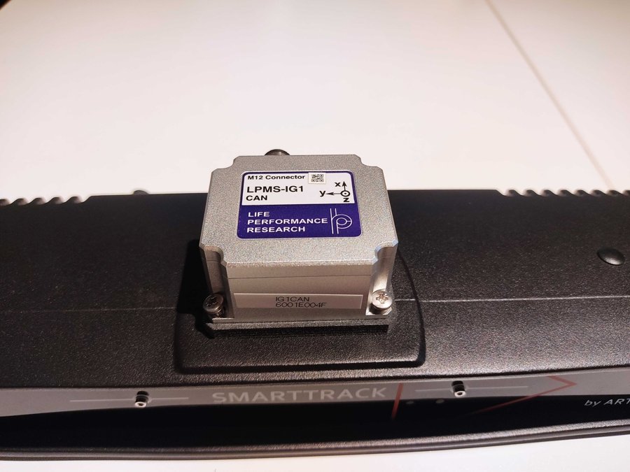
The finished unit looks like this. A video of the assembly is available at https://vimeo.com/968590559.
FusionHub configuration
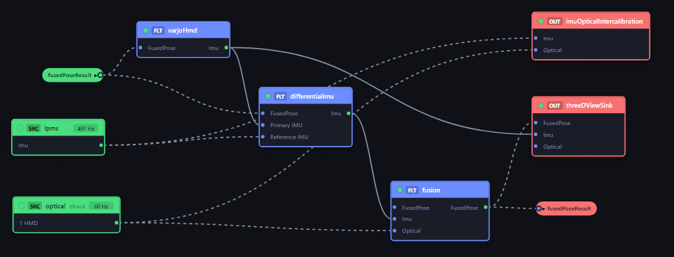
- On the Workspace page load the configuration LPVR-DUO Varjo ART. The node graph below is the standard LPVR-DUO graph for Varjo headsets.
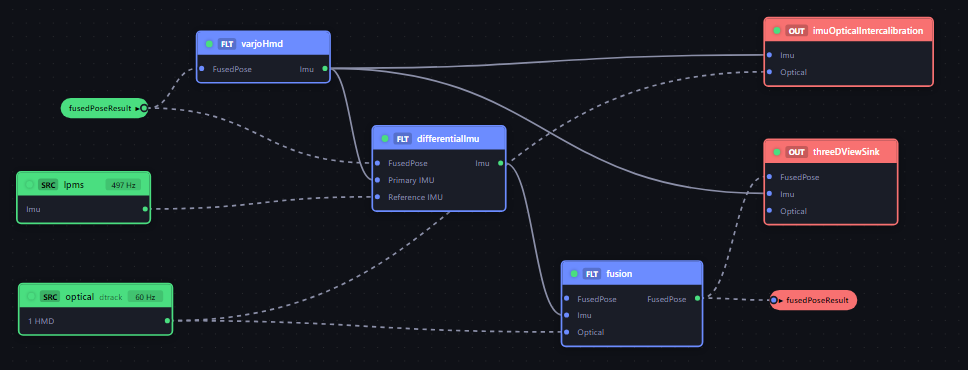
| Node | Purpose |
|---|---|
| lpms (LPMS Sensor) | Reads the LPMS-IG1 platform IMU over USB |
| optical (Optical Source, DTrack) | Receives the headset body pose from DTrack |
| varjoHmd (Varjo HMD) | Receives the headset IMU from the Varjo Base plugin and sends the fused pose back to Varjo Base |
| differentialImu (Differential IMU) | Subtracts the platform rotation from the headset IMU |
| fusion (IMU-Optical Fusion) | Fuses the differential IMU with the optical pose into the headset pose |
| imuOpticalIntercalibration | Calibration tool, only used for the optional calibrations below |
| threeDViewSink (3D View) | Shows the tracked headset in the 3D View page |
| fusedPoseResult port | Routes the fused pose back into the Varjo HMD and Differential IMU nodes |
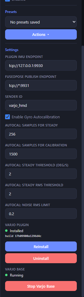
- Select the Varjo HMD node. Its properties panel installs the LPVR tracking plugin for Varjo Base. Click Install, then Start Varjo Base. If Varjo Base was already running during the installation, stop and start it again from this panel, since Varjo Base only scans for tracking plugins at startup.
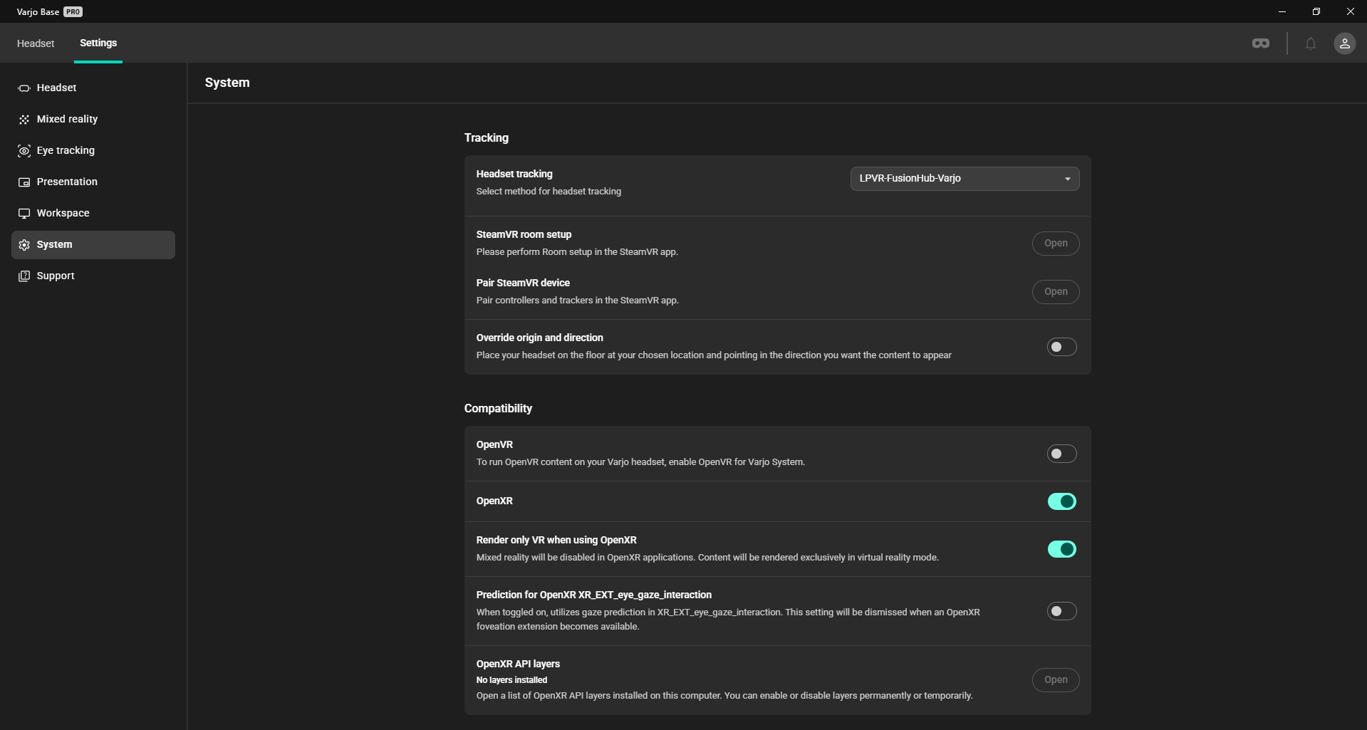
- In Varjo Base open Settings, go to the System page and under Headset tracking select LPVR-FusionHub-Varjo.
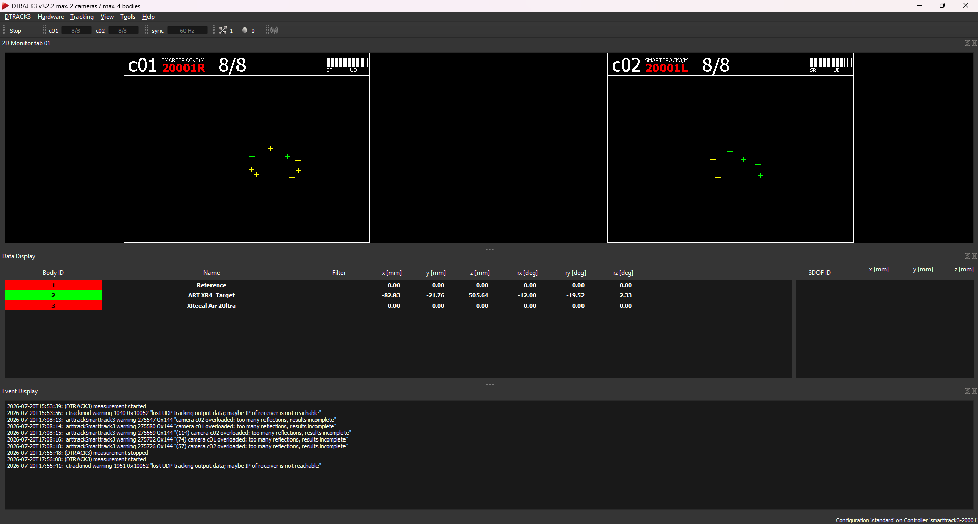
- In DTrack calibrate the headset target as a body, start the measurement and set the UDP output to the IP of the FusionHub PC and port 5000. Below you see the XR-4 target tracked in DTrack.
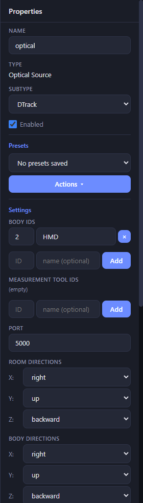
Select the optical node in FusionHub and check that the DTrack subtype, the body ID of the headset target and the UDP port match the DTrack output.
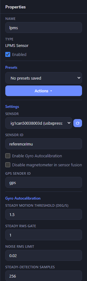
- Connect the LPMS-IG1 over USB and select the lpms node. Pick the IG1 from the Sensor dropdown (its name starts with
ig1; click the refresh button next to the dropdown if it is not listed yet). Keep Sensor ID atreferenceImuand leave gyro autocalibration off for the platform IMU.
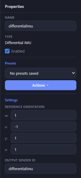
- The differentialImu node needs no changes. Its Primary IMU input is wired to the Varjo HMD node, the Reference IMU input to the lpms node, and its Reference Orientation already describes the IG1 in the slide holder with the connector pointing to the back.
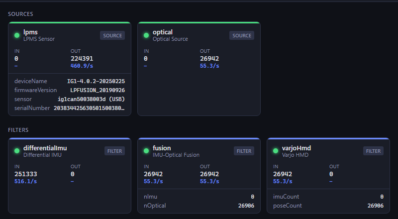
- Click Activate in the node editor. The Dashboard now shows the data rates: the lpms node runs at the IG1 sample rate, the optical node at the DTrack frame rate. The Varjo HMD node’s
imuCountstarts counting as soon as Varjo Base runs with the headset connected and LPVR-FusionHub-Varjo selected as tracking method.
Running the system
Start the components in this order:
- DTrack with the measurement running and the UDP output enabled.
- FusionHub. The saved configuration is activated at startup.
- Varjo Base with LPVR-FusionHub-Varjo selected as headset tracking method, then your VR or AR application.
On the Dashboard all three sources should show data, and the 3D View page shows the tracked headset.
Validation
- With the vehicle standing still, put on the headset. The scene follows head rotation smoothly and moves correctly when the headset is moved without rotation, e.g. lifted vertically.
- Drive a curve while looking straight ahead. Content that is fixed to the vehicle coordinate system keeps its position and orientation.
- If the scene rotates the wrong way when the vehicle turns, roughly twice as fast as the turn, the Primary and Reference IMU inputs of the Differential IMU node are swapped.
- If a vehicle turn shows up as a tilt, the Reference Orientation does not match how the IMU is mounted. Check the mounting or run the platform IMU calibration below.
Optional calibrations
You do not need this section for the standard package. It applies to custom setups:
| Situation | Calibration |
|---|---|
| ART headset target, IG1 in the slide holder with the connector to the back | None |
| Custom or self-built headset target | Headset IMU to marker target |
| IG1 mounted elsewhere on the camera or in a different orientation | Platform IMU to camera |
Both calibrations use the IMU-Optical Intercalibration node and the Calibration page.
Headset IMU to marker target
The rotation between the headset IMU and its marker target is calibrated exactly as for the static setup: follow the Varjo XR-4 section of the Headset Calibration Tutorials. The Intercalibration node’s IMU input is wired to the Varjo HMD node for this, and Reverse mode stays off. Do this with the vehicle standing still. It is needed once per marker target.
Platform IMU to camera
The platform IMU is rigidly attached to the SmartTrack 3, so the rotation between the IMU axes and the camera coordinate system is fixed. To measure it, the camera and IMU are moved together while the camera tracks a stationary body, typically the headset. FusionHub’s Reverse mode calibration does this comparison and writes the result into the Differential IMU node. Do this on the bench before the SmartTrack is mounted in the vehicle, because the camera has to be picked up and rotated freely.
- In the node editor connect the Imu output of the lpms node to the Imu input of the imuOpticalIntercalibration node, replacing the connection from the Varjo HMD node. The Optical input stays connected to the HMD body of the optical node. Click Activate.
-
Put the headset with its marker target on a stable support inside the field of view of the SmartTrack. It must not move during the calibration. The DTrack measurement must be running and the body tracked.
-
Open the Calibration page. IMU Input shows
referenceImu, Optical Input shows the HMD body. Tick Reverse mode (fixed optical target, IMU on the moving camera).
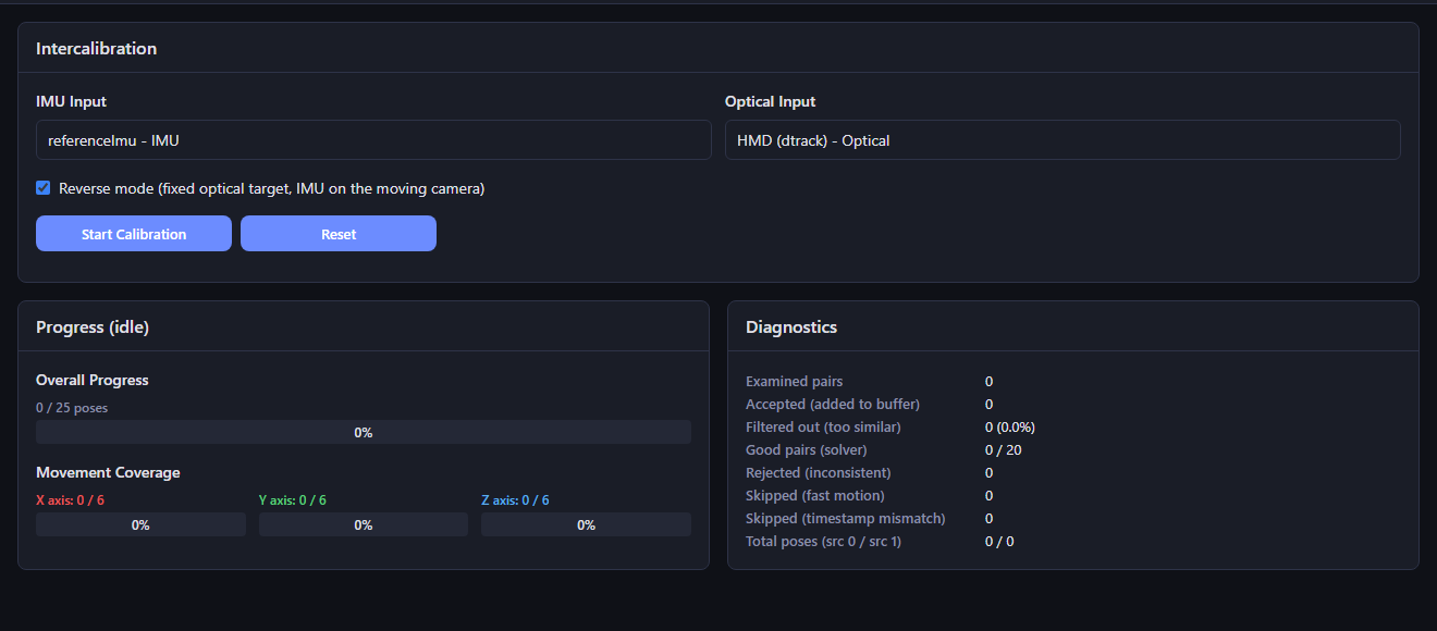
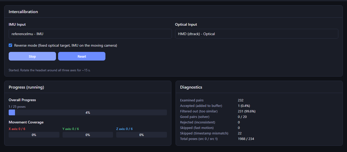
- Click Start Calibration. Pick up the SmartTrack with the IMU and rotate it slowly around all three axes while keeping the headset target in view. Pause briefly in a number of different orientations. Samples taken faster than about 9 deg/s are dropped, so gentle motion is what fills the bars. The page counts accepted poses toward 25, with at least 6 per axis. This typically takes 15-30 seconds.
-
When the bars are full the solver runs and the Result card shows the calibrated rotation. In Apply To the target differentialImu - Differential IMU (referenceOrientationQuat) is preselected in reverse mode. Click Apply to Configuration. The rotation is written into the Reference Orientation of the Differential IMU node.
-
Reconnect the Intercalibration node’s Imu input to the Varjo HMD node, click Activate and push the configuration to your workspace so it is not lost. The platform IMU must not be moved relative to the camera from now on. If you remount the IMU, repeat this calibration.
Troubleshooting
- lpms node shows no data rate: the IG1 was not found. Check the USB connection, refresh the Sensor dropdown and select the sensor again. The LPMS Control page shows all sensors FusionHub can see.
- optical node shows no data rate: check that the DTrack output points at the FusionHub PC and port 5000, that the measurement is running and that the Windows firewall allows FusionHub to receive UDP.
- Varjo HMD node stays at imuCount 0: Varjo Base is not running, the plugin is not installed, or LPVR-FusionHub-Varjo is not selected as tracking method. Restart Varjo Base after installing the plugin.
- Start Calibration is disabled: one of the inputs on the Calibration page reads Not connected. Fix the wiring in the node editor and activate the configuration.
- Many samples are skipped as fast motion during calibration: move the camera more slowly and pause between orientations.